Honeycomb filter

a filter and honeycomb technology, applied in the field of honeycomb filters, can solve the problems of difficult to increase the temperature of the entire honeycomb filter, increase the exhaust gas flow, etc., and achieve the effect of facilitating the removal of components contained

Active Publication Date: 2012-03-08
NGK INSULATORS LTD
View PDF18 Cites 14 Cited by
  • Summary
  • Abstract
  • Description
  • Claims
  • Application Information

AI Technical Summary

Benefits of technology

[0017]In a honeycomb filter according to an aspect of the present invention, at least one of the partition portion and the trapping layer may be loaded with a catalyst. The catalyst can facilitate the removal of components contained in a fluid, such as the removal of trapped solid components by combustion. The catalyst may burn unburned carbon-containing components contained in the fluid. This can further purify the fluid.

Problems solved by technology

However, this increases the permeation resistance of the partition and accordingly increases the exhaust gas flow to the downstream region.
Thus, it is difficult to increase the temperature of the entire honeycomb filter.
However, since the trapping layer in the upstream region has a large thickness, a larger amount of exhaust gas flows to the downstream region because of the Venturi effect, for example, under high flow rate conditions.

Method used


Image

  • Honeycomb filter
  • Honeycomb filter
  • Honeycomb filter

Examples


examples

[0048]Specific examples of the manufacture of a honeycomb filter will be described below.

[0049][Manufacture of Honeycomb Filter (DPF)]

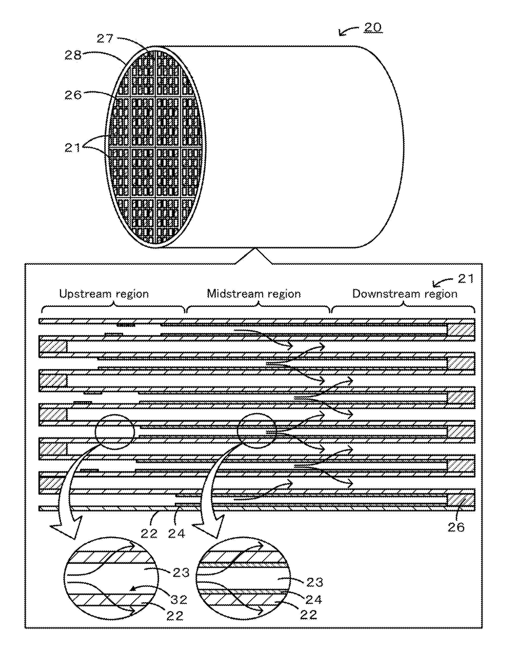
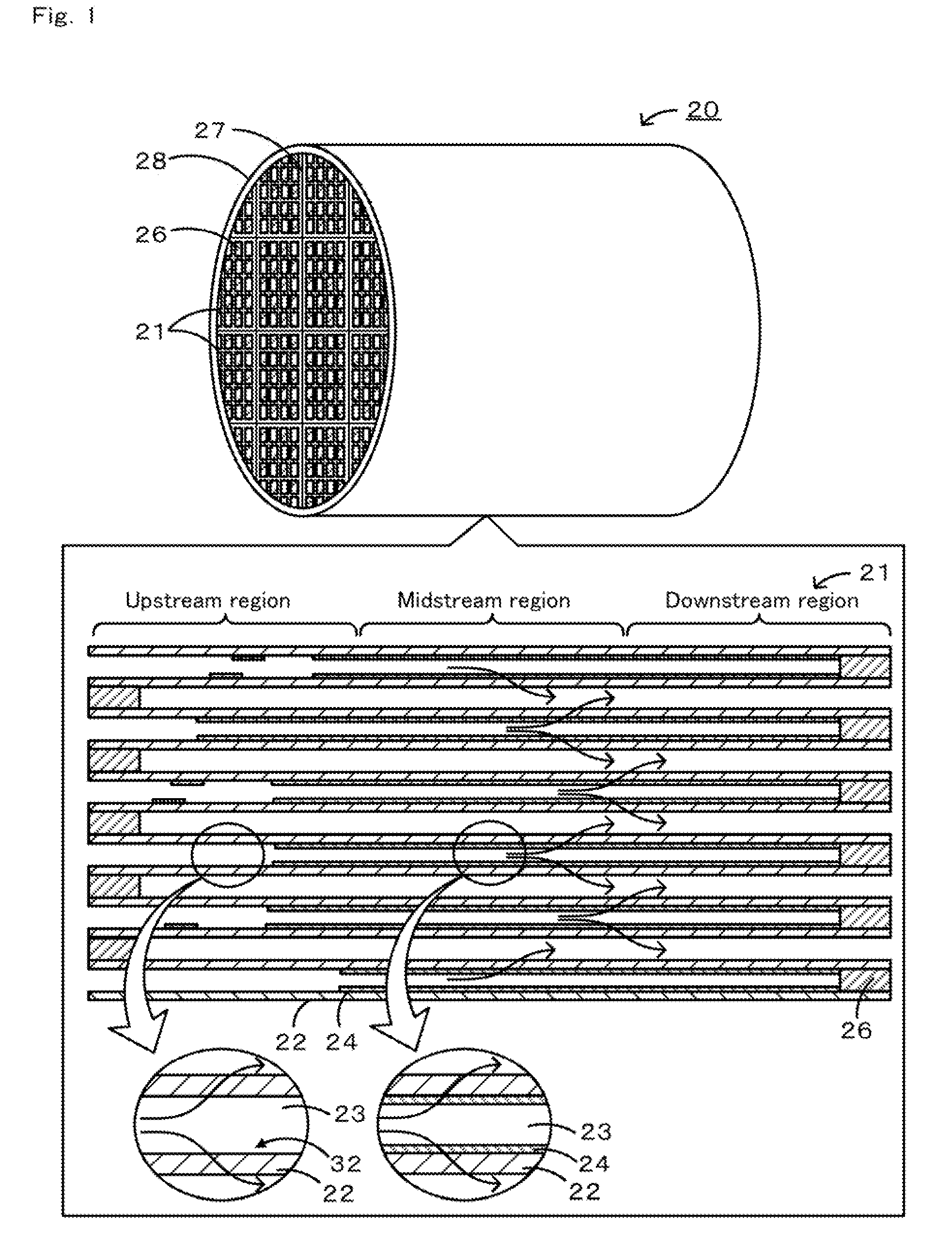
[0050]A SiC powder and a metallic Si powder were mixed at a mass ratio of 80:20. Methylcellulose, hydroxypropoxylmethylcellulose, a surfactant, and water were added to the mixture, which was then kneaded to prepare a plastic pug. The pug was extruded through a die to form a honeycomb segment formed product having a desired shape. The honeycomb segment was formed such that the cell shape in a cross section perpendicular to the exhaust gas flow direction was tetragonal, the thickness of the partition portion was 300 μm, the cell pitch was 1.47 mm, the cross section was 35 mm×35 mm, and the length was 152 mm. The honeycomb segment formed product was dried using a microwave and then with hot air, was sealed, was calcined in an oxidizing atmosphere at 550° C. for three hours, and was baked in an inert atmosphere at 1400° C. for two hours. The sealing porti...

examples 1 to 6

[0059]In accordance with the conditions for manufacturing the honeycomb filter described above, a honeycomb segment was formed such that the thickness of the partition portion was 304.8 μm and the cell width was 1.16 μm square. The thickness distribution treatment of the trapping layer was performed such that the undeposited region length percentage was 5%, the undeposited region area percentage in a cross section was 100%, and the average thickness of the trapping layer was 40 μm. The resulting honeycomb filter was referred to as Example 1. Honeycomb filters manufactured in the same manner as in Example 1 except that the undeposited region length percentage was 10%, 15%, 20%, 25%, or 30% were referred to as Examples 2 to 6, respectively.

examples 7 to 14

[0061]The thickness distribution treatment of the trapping layer was performed under the same conditions for manufacturing the honeycomb filter described above except that the undeposited region length percentage was 15%, the average thickness of the trapping layer was 40 μm, and the undeposited region area percentage in a cross section was 6%, 8%, 10%, 15%, 20%, 30%, 50%, or 80%. The resulting honeycomb filters were referred to as Examples 7 to 14, respectively.

[0062][Measurement of Purification Efficiency]

[0063]The DOC and the DPF manufactured as described above were subjected to aging. Simulating the mileage of approximately 200,000 km, the DOC and the DPF were subjected to aging in the atmosphere at 850° C. for 10 hours. After aging, the purification efficiency, the pressure loss due to PM deposition, and the PM trapping efficiency of the DOC and the DPF were measured. For the measurement of purification efficiency, 8 g / L of PM was deposited at 2500 rpm at 60 Nm on the DOC and t...


PUM

PropertyMeasurementUnit
partition thickness tpaaaaaaaaaa
thickness tpaaaaaaaaaa

Abstract

A honeycomb filter includes a cell having one open end and another closed end that serves as a fluid flow path and a cell having one closed end and another open end, wherein the cells are alternately disposed. The honeycomb filter includes an undeposited region in an upstream region of a partition portion, which has no trapping layer and has a length of 5% or more and 30% or less of the length of the inlet cell. The upstream region of the partition portion includes an undeposited region having an area of 10% or more of that of the cell in a cross-section perpendicular to the exhaust gas flow direction. The undeposited region with no trapping layer in the upstream region decreases the permeation resistance of the partition portion in the upstream region and facilitates fluid passage through the partition portion in the upstream region.

Description

TECHNICAL FIELD[0001]The present invention relates to a honeycomb filter.[0002]One proposed honeycomb filter includes a porous partition portion, in which a cell that is open at one end and closed at the other end and a cell that is closed at one end and open at the other end are alternately disposed, and a layer for trapping and removing particulate matter (hereinafter also referred to as PM) contained in an exhaust gas formed on the partition portion (see, for example, Patent Documents 1 to 3). This honeycomb filter can trap PM by the trapping layer with low pressure loss.[0003]In another proposed honeycomb filter, a trapping layer formed on a partition portion has a decreased thickness in the central region of the honeycomb filter in the exhaust gas flow direction (see, for example, Patent Document 4). In this honeycomb filter, the permeation resistance of a partition in the central region, which generally has low exhaust gas permeability, can be decreased to increase the exhaust...

Claims


Application Information

Patent Timeline
Patent Type & Authority Applications(United States)
IPC IPC(8): B01D53/94B01D39/20
CPCB01D53/944B01D2255/1021B01D2255/2065B01D2255/2092B01D2255/9032F01N2510/0682F01N3/022F01N3/0222F01N3/035F01N3/2842F01N2330/60B01J35/04B01D46/247B01D46/2474B01D46/2429B01D46/2484B01D46/2482B01D46/2478B01D46/24492
Inventor MIZUTANI, TAKASHINAGATA, KOJIMIYAIRI, YUKIO
Owner NGK INSULATORS LTD
Why Eureka
Try Eureka