

Photovoltaic module
- Summary
- Abstract
- Description
- Claims
- Application Information
AI Technical Summary
Benefits of technology
Problems solved by technology
Method used
Image

Examples
first embodiment
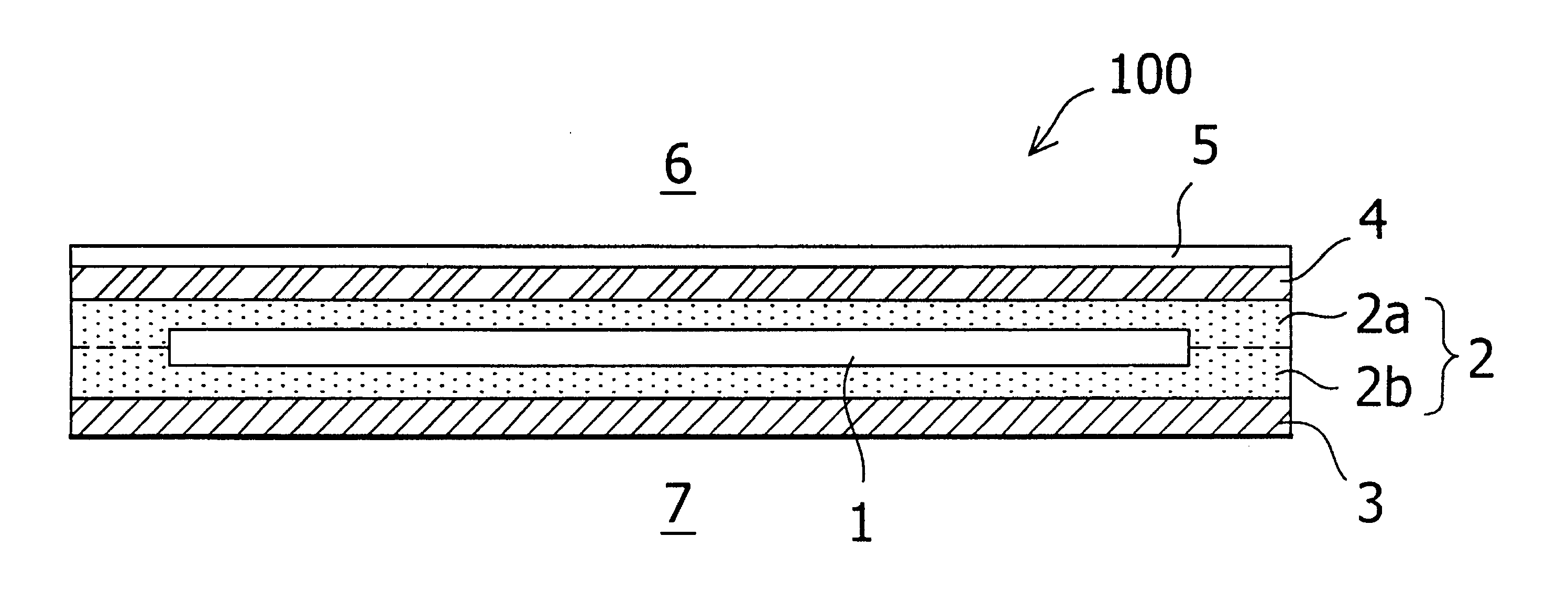
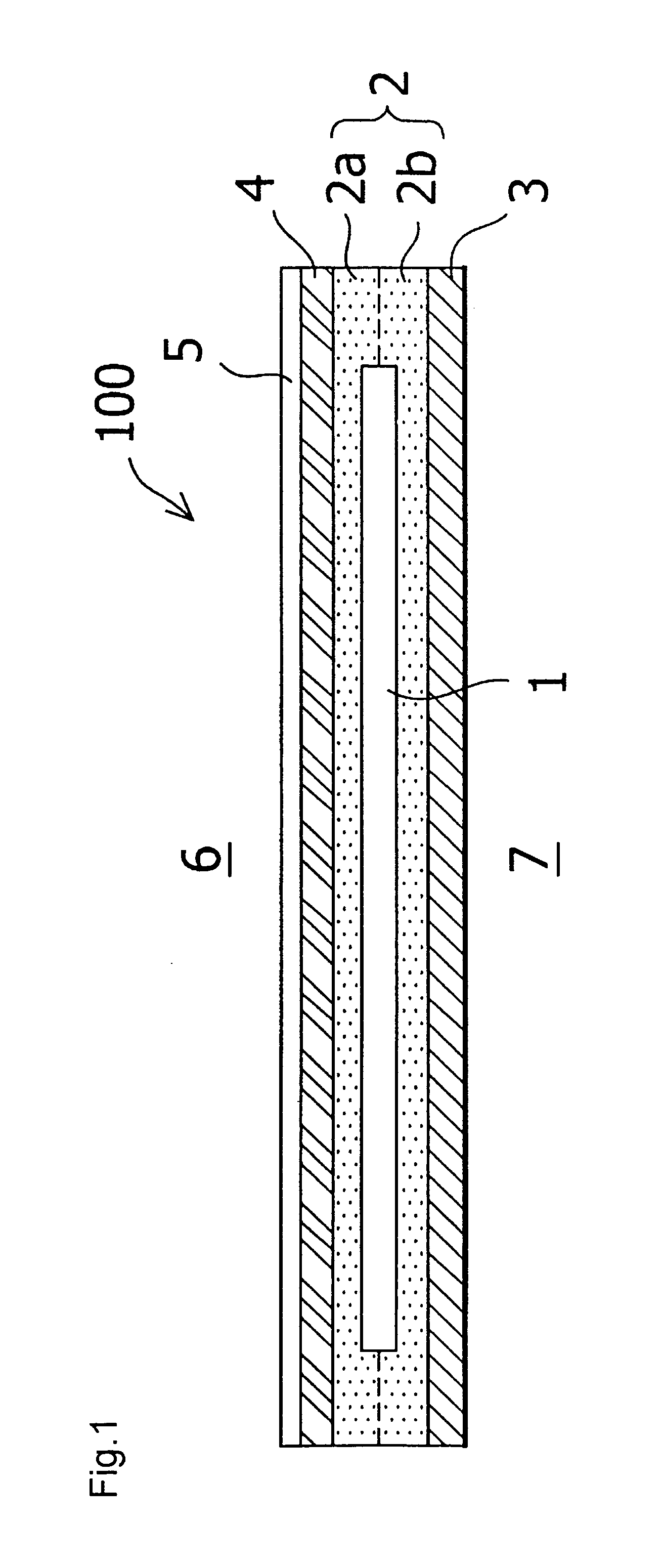
[0020]A photovoltaic module 100 of a first embodiment according to the invention is such that while a front surface protection layer 4 is joined to a light receiving surface side 6 of a substrate structure photovoltaic cell 1 through a sealing member layer 2a, a rear surface protection layer 3 is joined to a non-light receiving surface side 7 of the photovoltaic cell 1 through a sealing member layer 2b, and furthermore, a glass coating layer 5 is formed on an outermost surface of the front surface protection layer 4, as shown in FIG. 1.
[0021]The photovoltaic cell 1 is such that while a metal electrode layer 12 of Ag, Al, or the like, is deposited on the front surface of a film substrate 11, a photoelectric conversion layer 13 formed from a p-i-n junction structure amorphous silicon semiconductor film is deposited on the metal electrode layer 12, and furthermore, a transparent electrode layer 14 formed from ITO, ZnO, or the like, is formed on the photoelectric conversion layer 13; a ...
third embodiment
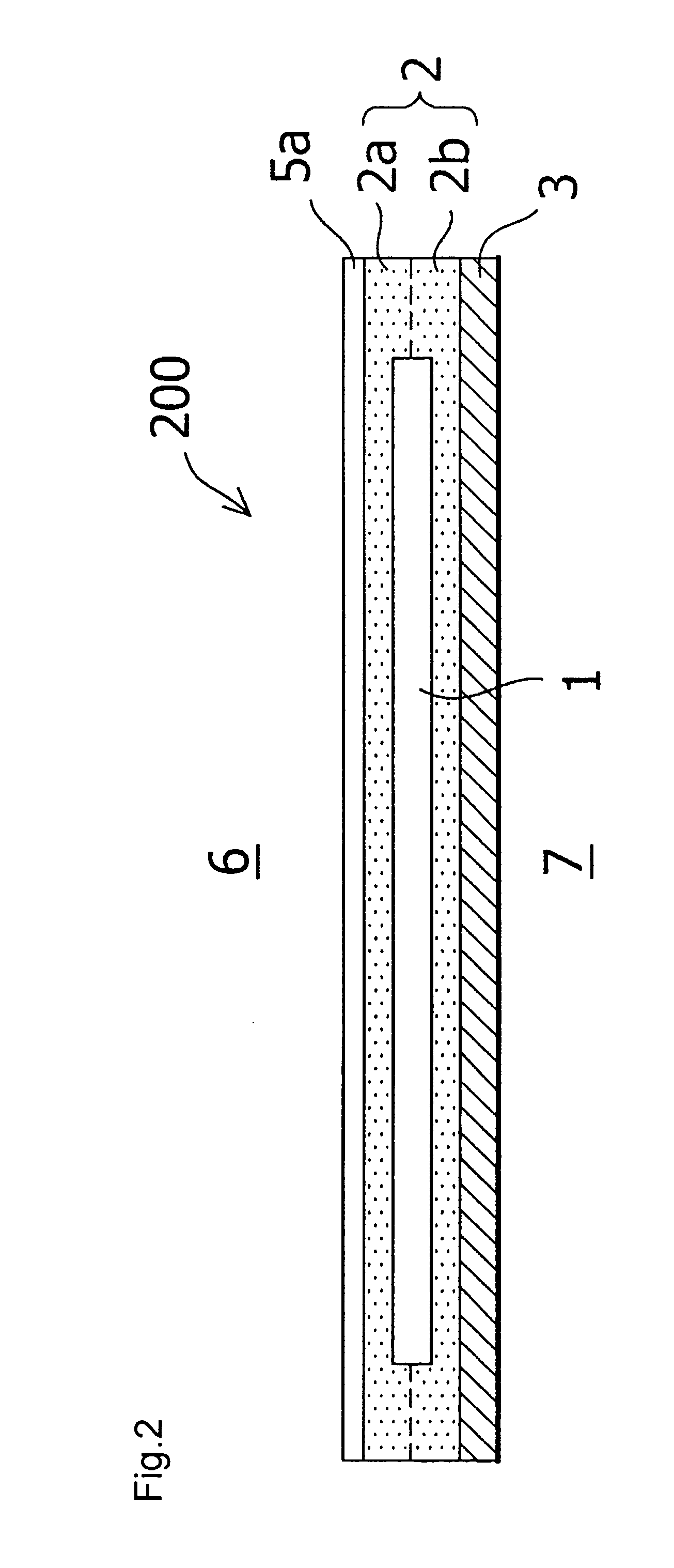
[0029]As the front surface protection member 4 is directly exposed to flame in the photovoltaic module 300 of the third embodiment, the flame resistance of the module surface depends on the material of the front surface protection member 4, and thus there is no difference from a heretofore known module. However, as the heat resistance of the film substrate 11 of the photovoltaic cell 1 improves, and deformation due to the heat of a flame is suppressed, by interposing the glass coating layer 5b on the light receiving surface side 6 of the photovoltaic cell 1; an improvement in flame resisting performance as a module can be expected because of this.
[0030]Although a description has been given of some embodiments of the invention, the invention is not limited to these embodiments, and various other further modifications and changes are also possible based on the technical idea of the invention.
[0031]For example, in the embodiments, a case is shown wherein the preliminary lamination proc...
PUM
| Property | Measurement | Unit |
|---|---|---|
| Temperature | aaaaa | aaaaa |
| Transparency | aaaaa | aaaaa |
Abstract
Description
Claims
Application Information