Bio-oil production with optimal byproduct processing

Inactive Publication Date: 2012-03-22
MARD INC
View PDF10 Cites 13 Cited by
  • Summary
  • Abstract
  • Description
  • Claims
  • Application Information

AI Technical Summary

Problems solved by technology

Although many of these biomass conversion processes can produce high yields of bio-oil, most, if not all, of the bio-oil produced is of low quality due to the high amounts of oxygen present in the bio-oil.
Due to the high amounts of oxygen, these low quality bio-oils require extensive secondary upgrading in order to be utilized as transportation fuels and

Method used


Image

  • Bio-oil production with optimal byproduct processing
  • Bio-oil production with optimal byproduct processing
  • Bio-oil production with optimal byproduct processing

Examples


example

[0049]For the separate runs listed in Table 1 below, wood was charged to a pyrolysis reactor for contact with kaolin and zeolite catalysts at different inlet riser reaction temperatures. Results from the runs are set out in Table 1 below.

TABLE 1LowHighLowHighSeveritySeveritySeveritySeverityKaolinKaolinZeoliteZeoliteRiser Inlet Temp. (° F.)1230126512301265Cat / feed ratio (wt / wt)13.531.213.322.9CO / Bio-oil ratio (wt / wt)0.716.411.004.09Methane / Bio-oil ratio (wt / wt)0.070.700.050.32Hydrogen / Bio-oil ratio (wt / wt)0.010.090.010.03

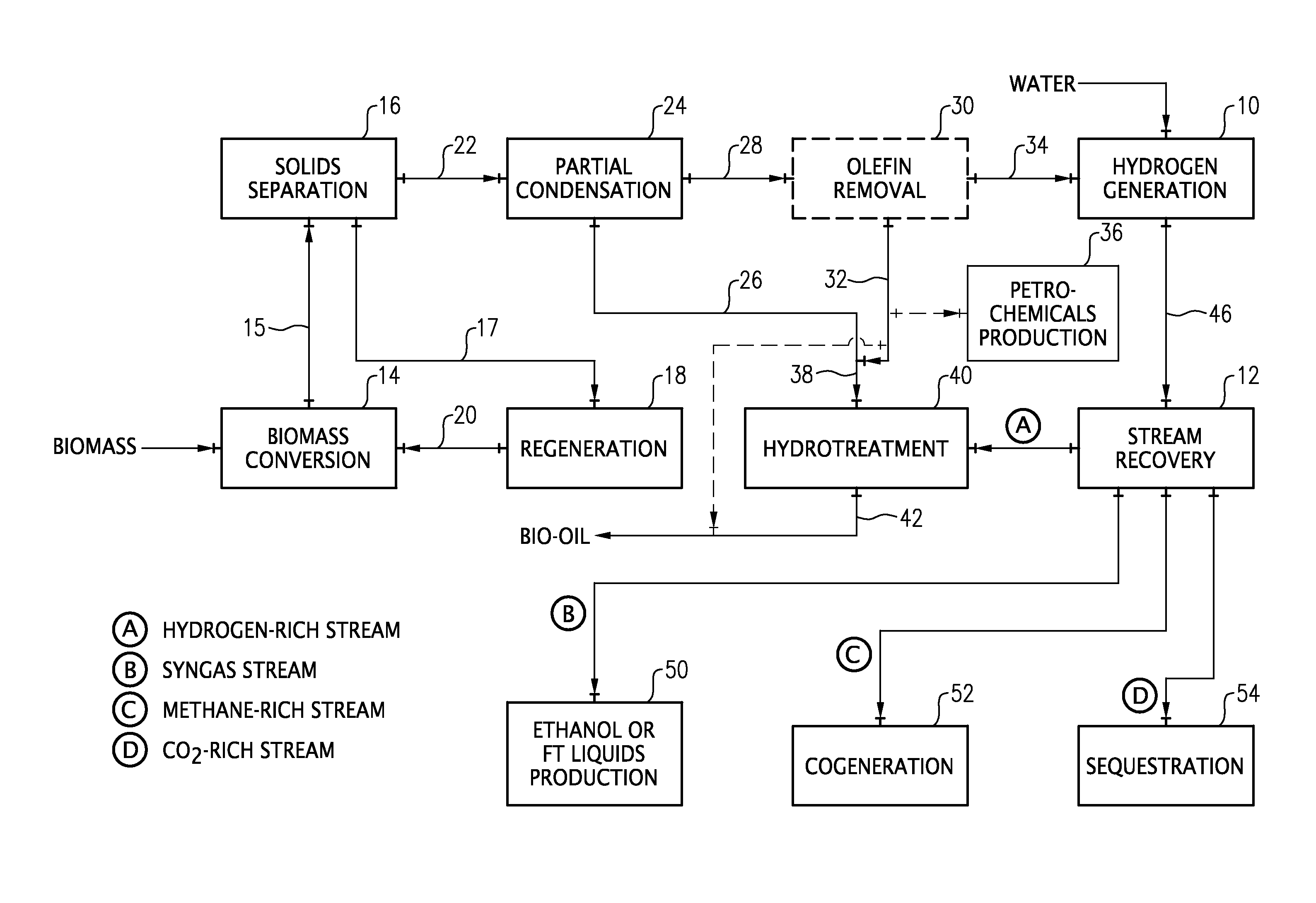
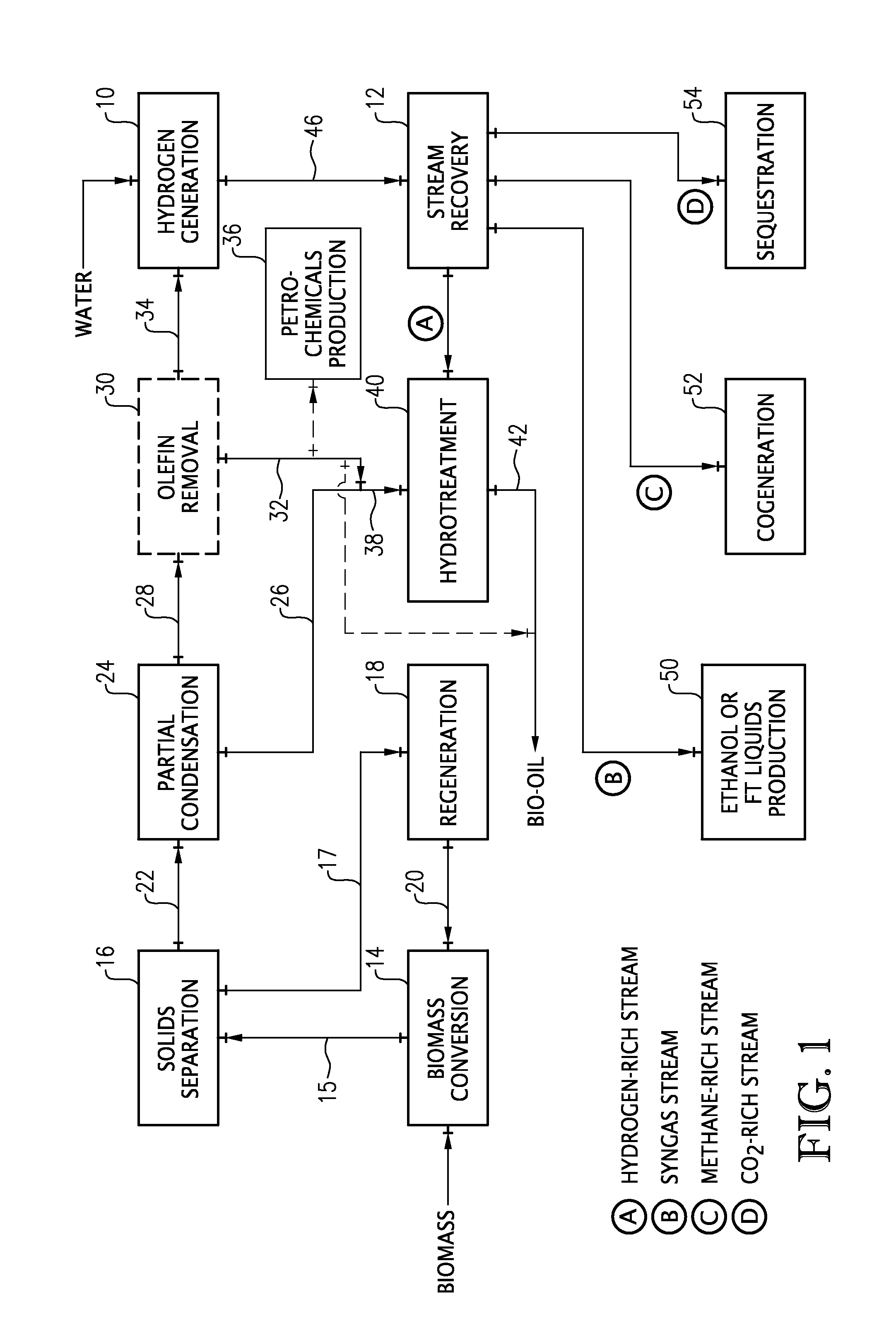
[0050]As can be seen from Table 1 above, as the severity of the biomass conversion is increased (increased temperature and increased catalyst to feed ratio), the weight ratios of CO, methane, and hydrogen to bio-oil all increase. In particular, the increases in CO and methane resulting from the high severity runs are sufficient to generate enough hydrogen to adequately hydrotreat the produced bio-oil without requiring hydrogen from external sources.


PUM


Abstract

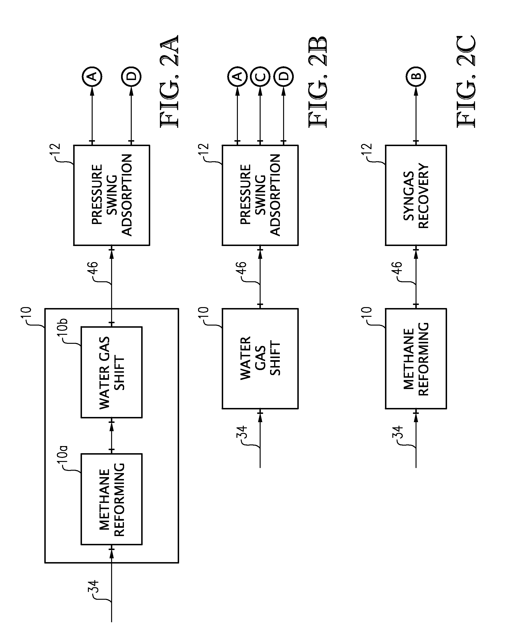
A process and system for the conversion of biomass under high severity in the presence of a catalyst to produce a bio-oil, olefins, methane, and carbon monoxide (CO). The methane and/or CO can be used to generate hydrogen and the generated hydrogen can be used for hydrotreating the bio-oil. Additionally, or alternatively, a syngas stream, a carbon dioxide-rich stream, and/or a methane-rich stream can be recovered for use in the bio-oil production process and/or for use in a conventional petroleum refinery and/or petrochemical plant.

Description

BACKGROUND[0001]1. Field of the Invention[0002]The present invention relates generally to the conversion of biomass under high severity to produce high quality bio-oil and byproducts, wherein the byproducts can be recovered and / or processed to provide one or more commercially valuable streams.[0003]2. Description of the Related Art[0004]With the rising costs and environmental concerns associated with fossil fuels, renewable energy sources have become increasingly important. The development of renewable fuel sources provides a means for reducing the dependence on fossil fuels. Accordingly, many different areas of renewable fuel research are currently being explored and developed.[0005]With its low cost and wide availability, biomass has increasingly been emphasized as an ideal feedstock in renewable fuel research. Consequently, many different conversion processes have been developed that use biomass as a feedstock to produce useful biofuels and / or specialty chemicals. Existing biomas...

Claims


Application Information

Patent Timeline
IPC IPC(8): C10B57/00
CPCC01B3/16C10G2300/42C01B2203/0233C01B2203/0283C01B2203/043C01B2203/1241C10B49/22C10B53/02C10G2/30C10G3/52C10K1/005Y02E50/14Y02E50/32C10G2400/20C10G2300/1011C01B3/38Y02E50/10Y02E50/30Y02P20/145Y02P30/40
Inventor DITSCH, ANDRE
Owner MARD INC
Why Eureka
Try Eureka