In-line fuel conditioner

a fuel conditioner and fuel technology, applied in the field of fuel conditioners, can solve the problems of engine emissions, environmental degradation, carbon monoxide, hydrocarbons and nitrogen oxides, etc., and achieve the effect of improving fuel combustibility and reducing emissions

Active Publication Date: 2012-03-22
IRVIN WALLACE TAYLOR
View PDF2 Cites 28 Cited by
  • Summary
  • Abstract
  • Description
  • Claims
  • Application Information

AI Technical Summary

Benefits of technology

[0007]The present invention provides for a fuel conditioner placed in-line a fuel delivery system for internal combustion engines using gasoline or diesel fuel that is designed to improve fuel combustibility and reduce emissions. The in-line fuel conditioner also provides the additional benefit of collecting ferrous particles before the particles enter and cause harm to the engine.
[0009]In another aspect, the present invention provides an in-line fuel conditioner wherein the second housing forms a seal around the magnet such that the liquid fuel does not contact the magnet. Such a seal provides the benefit of protecting the magnet from corrosion.
[0010]In a further aspect, the present invention provides an in-line fuel conditioner that includes a configuration wherein the second housing is placed within the sealed chamber such that liquid fuel may follow a flow path around all sides of the magnet that is disposed within the second housing. This may allow for the benefit of a greater density of the fuel to be exposed to the magnetic field by staying in closer proximity to the magnet.
[0013]In yet a further aspect, the invention provides for an in-line fuel conditioner that includes an exit fuel line in fluid communication with a fuel outlet and an electromagnetic shield encasing the fuel exit line. The electromagnetic shield may protect the conditioned fuel from external magnetic and electromagnetic fields before the fuel enters the engine.
[0015]Furthermore, the invention provides for a flow tube to be disposed in the sealed chamber of the in-line fuel conditioner in another aspect of the invention. The flow tube connects a hole in the upstream plate to a hole in the downstream plate. The flow tube may be arranged in a helical pattern in the sealed chamber. The helical pattern provides the advantage of increasing the amount of time the fuel spends passing through the sealed chamber, and thus increasing the beneficial effects of the magnetic field on the fuel.
[0017]In yet a further aspect, the present invention provides for an in-line fuel conditioner that has an outer surface of the upstream plate and an outer surface of the downstream plate in sealing engagement with the first housing such that the flow path of the liquid fuel is constrained to flowing from the fuel inlet through the hole in the upstream plate, the chamber, the hole in the downstream plate, and the fuel outlet. An axis of the hole in the upstream plate may be configured such that the axis of the hole is at an angle with respect to the longitudinal axis of the in-line fuel conditioner. The angled hole in the upstream plate may cause beneficial turbulence in the fuel flow path.

Problems solved by technology

However, these engines may also emit harmful toxins to the atmosphere due to incomplete combustion of fuel.
Specifically, incomplete combustion of fuel may lead to emissions of carbon monoxide, hydrocarbons, and nitrogen oxides.
These gases may be poisonous and lead to the degradation of the environment by producing smog and acid rain.
While only small traces of these gases may be emitted from any specific engine due to incomplete combustion of fuel, the overall amount of these harmful emissions and their effects on the environment are quite large and drastic when considering the world-wide use of internal combustion engines burning gasoline or diesel fuels.

Method used


Image

  • In-line fuel conditioner
  • In-line fuel conditioner
  • In-line fuel conditioner

Examples


Embodiment Construction

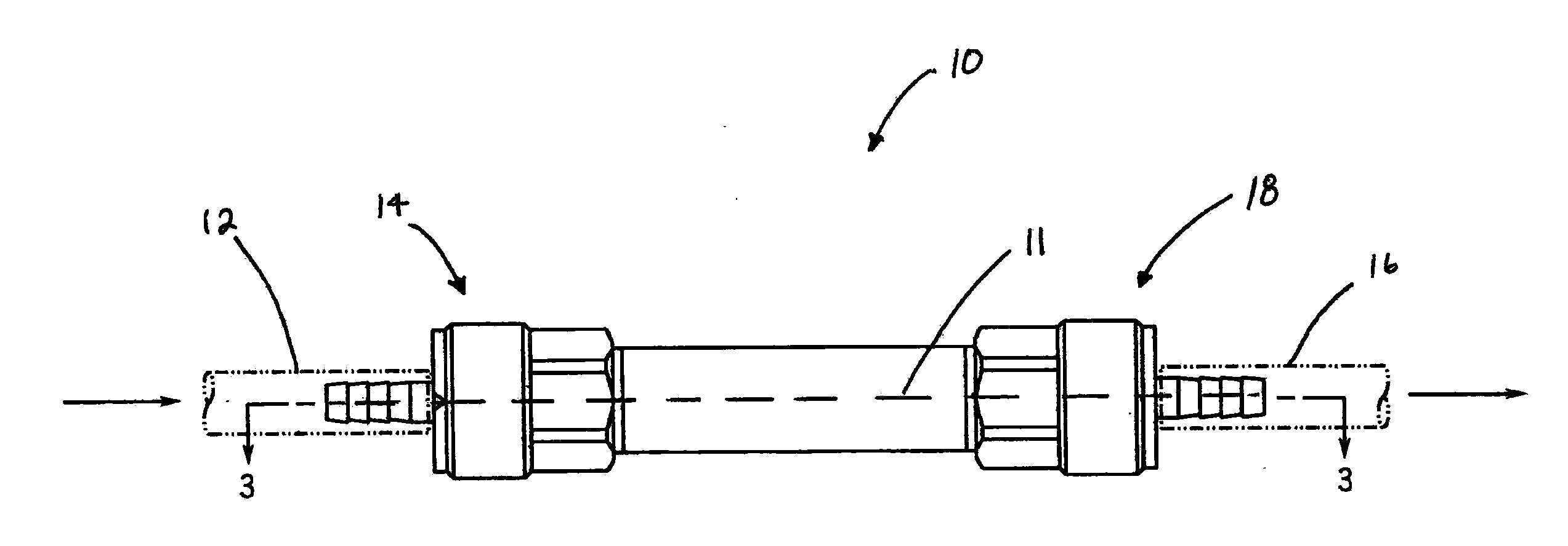
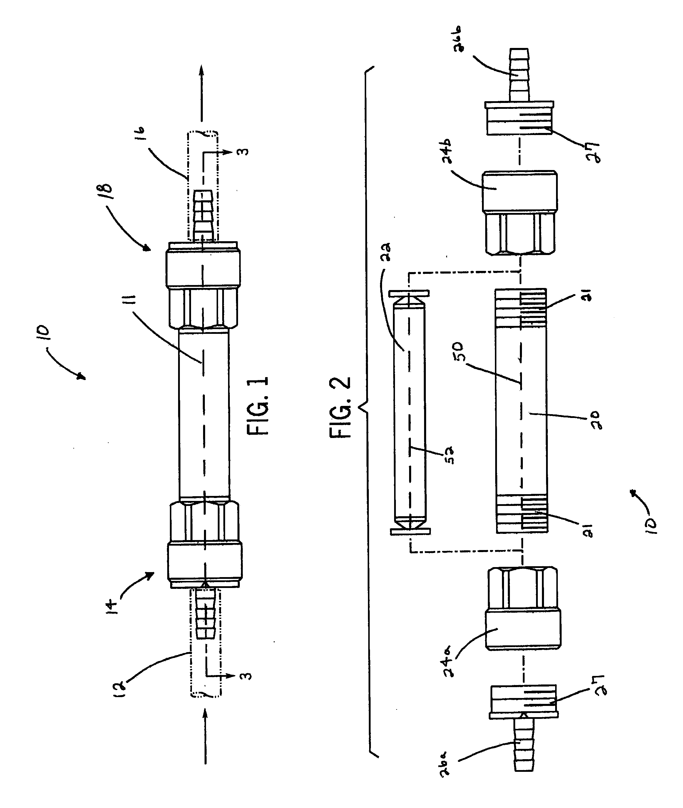
[0029]FIG. 1 displays the in-line fuel conditioner 10 in its assembled state placed in-line a fuel delivery system. The arrows in FIG. 1 show the direction fuel generally flows through the fuel delivery system for the internal combustion engine (not shown) through a longitudinal axis 11 of the in-line fuel conditioner 10. The in-line fuel conditioner 10 may be placed downstream of a fuel pump (not shown) and fuel filter (not shown)—if the apparatus with the internal combustion engine has such features—but is placed upstream of the fuel injection apparatus (not shown) that delivers fuel to the internal combustion engine. As seen in FIG. 1, the fuel line can be described as an entrance fuel line 12, which is in fluid communication with the fuel inlet 14 of the in-line fuel conditioner 10, and an exit fuel line 16, which is in fluid communication with the fuel outlet 18 of the in-line fuel conditioner 10.

[0030]Referring now to FIG. 2, the in-line fuel conditioner 10 is shown partially ...


PUM

PropertyMeasurementUnit
magneticaaaaaaaaaa
magnetic polesaaaaaaaaaa
angleaaaaaaaaaa

Abstract

A fuel conditioner is provided for improving fuel combustibility and reducing emissions into the environment. The fuel conditioner may be placed in-line in a fuel delivery system for internal combustion engines and may include the following components: a first housing defining a sealed chamber, a fuel inlet in fluid communication with the sealed chamber, a second housing disposed within the sealed chamber, a magnet disposed in the second housing, a fuel outlet in fluid communication with the sealed chamber, and a flow path in the sealed chamber for flow of the liquid fuel between the fuel inlet and the fuel outlet. Along its flow path, the liquid fuel is split apart and passes through magnetic fields due to one or more magnets inside the second housing to condition the fuel to improve fuel combustibility and reduce toxic emissions.

Description

CROSS REFERENCE TO RELATED APPLICATIONS[0001]This application claims the benefit of U.S. Provisional Patent Application No. 61 / 383,652 filed Sep. 16, 2010 which is incorporated in its entirety herein for all purposes.STATEMENT OF FEDERALLY SPONSORED RESEARCH OR DEVELOPMENT[0002]Not applicable.BACKGROUND OF THE INVENTION[0003]The invention relates to a fuel conditioner configured to be used in-line in a fuel delivery system for an internal combustion engine and is designed to improve fuel combustibility and reduce harmful emissions.[0004]Internal combustion engines are used in wide variety of applications including, but not limited to, automobiles, trucks, motorcycles, boats, aircraft, generators, and mobile equipment. During the application of such internal combustion engines, several substances are emitted as exhaust, such as carbon dioxide and water. However, these engines may also emit harmful toxins to the atmosphere due to incomplete combustion of fuel. Specifically, incomplete...

Claims


Application Information

Patent Timeline
Patent Type & Authority Applications(United States)
IPC IPC(8): B03C1/02
CPCB03C1/0332B03C1/286B03C2201/30B03C2201/20B03C2201/18
Inventor IRVIN, WALLACE TAYLOR
Owner IRVIN WALLACE TAYLOR
Why Eureka
Try Eureka