Light emissive ceramic laminate and method of making same

a technology of light emissive ceramics and laminates, applied in the field ofluminescent layers, can solve the problems of poor luminosity, increased cost, and increased cost of co-fired laminated layers

Inactive Publication Date: 2012-03-22
NITTO DENKO CORP
View PDF8 Cites 50 Cited by
  • Summary
  • Abstract
  • Description
  • Claims
  • Application Information

AI Technical Summary

Problems solved by technology

Nevertheless, while being appropriate for color conversion, the thin phosphor layers are rendered fragile and difficult to handle.
However, co-fired laminated layers suffer from additional problems.
Since some of these laminated layers are generally formed from garnet powders produced through solid state reaction, the present inventors recognized that using these garnet powders can result in poor luminosity once the gues

Method used


Image

  • Light emissive ceramic laminate and method of making same
  • Light emissive ceramic laminate and method of making same
  • Light emissive ceramic laminate and method of making same

Examples


example 1

YAG:Ce / Al2O3 / YAG and YAG:Ce / YAG Ceramic Composite Preparation and Optical Performance Measurement

[0069]a. Plasma Raw Powder Used for YAG:Ce Green Sheet Preparation

[0070]Plasma synthesized YAG powder (5 g) containing 1.75 mol % cerium with respect to yttrium was added to a high purity alumina combustion boat and annealed in a tube furnace (MTI GSL 1600) at 1200° C. for about 2 hours under flowing gas mixture of 3% H2 and 97% N2. A BET surface area of annealed YAG powders was measured to be about 5.5 m2 / g. The annealed YAG powder was used for YAG:Ce green sheet preparation.

[0071]b. Al2O3 Raw Powder Used for Al2O3 Green Sheet Preparation

[0072]Al2O3 (5 g, 99.99%, grade AKP-30, Sumitomo Chemicals Company Ltd.) with a BET surface area of of 6.6 m2 / g was used for the Al2O3 green sheet preparation.

[0073]c. Solid State Reaction (SSR) Raw Powder Used for YAG Green Sheet Preparation

[0074]Y2O3 powder (2.846 g, 99.99%, lot N-YT4CP, Nippon Yttrium Company Ltd.) with a BET surface area of 4.6 m2 / g...

example 2

[0088]Plural green sheets comprising SSR YAG (without the emissive guest materials, e.g., Ce) having a thickness of 200 μm each were produced by following the procedure set forth in EXAMPLE 1.

[0089]One green sheet of 90 μm comprising plasma YAG containing Ce3+ as an activator of 1.75 mol % with respect to yttrium was produced according to the procedures of EXAMPLE 1.

[0090]One green sheet of 50 um comprising Al2O3 was produced by following the procedures of EXAMPLE 1.

[0091]Two pieces of SSR YAG cut cast tapes (0% Ce, 200 μm each) and one piece of plasma YAG cut cast tape (1.75 mol % Ce, 90 μm) (YAG:Ce / SSR YAG 1 / SSR YAG2) were used to get the first laminated green sheet. The first ceramic composite as shown in FIG. 6 was produced by following procedures in EXAMPLE 1 for debindering, first sintering, second sintering and reoxidation.

[0092]Two pieces of SSR YAG cut cast tapes (0% Ce, 200 μm each), one piece of Al2O3 cut cast tape (50 μm) and one piece of plasma YAG cut cast tape (1.75 m...

example 3

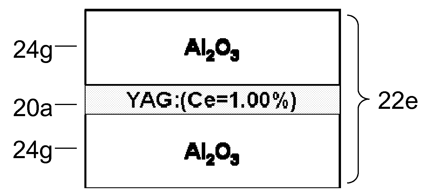
[0095]Two piece of Al2O3 cut cast tapes (120 μm each) 24g and one piece of plasma YAG cut cast tape (1.00 mol % Ce, 45 μm) 20a are layered with the plasma YAG piece placed between the Al2O3 pieces to get the laminated green sheet (FIG. 10). The ceramic composite are produced by following procedures in EXAMPLE 1 for debindering, first sintering, second sintering and reoxidation. TOF-SIMS (Time-Of-Flight Secondary Ion Mass Spectroscopy) will be performed for composition analysis. With the current thickness of Al2O3 sheet, it is anticipated that Ce will be fully constrained with the plasma YAG layer even though the used Ce doping concentration can be as high as 1.00 mol %.


PUM

PropertyMeasurementUnit
Fractionaaaaaaaaaa
Fractionaaaaaaaaaa
Thicknessaaaaaaaaaa

Abstract

A laminated composite includes a wavelength-converting layer and a non-emissive blocking layer, wherein the emissive layer includes a garnet host material and an emissive guest material, and the non-emissive blocking layer includes a non-emissive blocking material. The metallic element constituting the non-emissive blocking material has an ionic radius which is less than about 80% of an ionic radius of an A cation element when the garnet or garnet-like host material is expressed as A3B5O12 and/or an element constituting the emissive guest material, and the non-emissive blocking layer is substantially free of the emissive guest material migrated through an interface between the emissive layer and the non-emissive blocking layer.

Description

CROSS-REFERENCE TO RELATED APPLICATIONS[0001]This application claims the benefit of U.S. Provisional Application No. 61 / 384,536, filed Sep. 20, 2010, the disclosure of which is herein incorporated by reference in its entirety.BACKGROUND OF THE INVENTION[0002]1. Field of the Invention[0003]This disclosure relates to luminescent layers suitable for light-emitting devices, such as translucent ceramic sheets composed of emissive and non-emissive blocking layers and methods of making the same.[0004]2. Description of the Related Art[0005]Solid state light-emitting devices such as light-emitting diodes (LEDs), organic light-emitting diodes (OLEDs) sometimes called organic electroluminescent devices (OELs), and inorganic electroluminescent devices (IEL) have been widely utilized for various applications such as flat panel displays, indicators for various instruments, signboards, and ornamental illuminations, etc. As the emission efficiency of these light-emitting devices continues to improv...

Claims


Application Information

Patent Timeline
IPC IPC(8): H01L33/50B32B37/14B32B37/06B32B19/00B32B3/00
CPCB32B18/00Y10T428/265C01P2002/84C01P2006/12C04B35/44C04B35/6261C04B35/6265C04B35/62665C04B35/62685C04B35/63488C04B35/638C04B2235/3217C04B2235/3222C04B2235/3225C04B2235/3229C04B2235/5409C04B2235/6025C04B2235/6562C04B2235/6581C04B2235/6587C04B2235/661C04B2235/663C04B2235/764C04B2235/9653C04B2237/341C04B2237/343C04B2237/562C04B2237/565C04B2237/704C09K11/7774H01L33/505C01F17/0025C01F17/34
Inventor ZHANG, BINPAN, GUANGMIYAGAWA, HIROAKIFUJII, HIRONAKAMUKHERJEE, RAJESHNAKAMURA, TOSHITAKA
Owner NITTO DENKO CORP
Why Eureka
Try Eureka