Antennas

a technology of antenna array and antenna array, which is applied in the direction of direction finders using radio waves, instruments, and reradiation, etc., can solve the problems of inability to analyze inability to use the measurement method based on the time of flight, and high cost of radar and other problems, to achieve the effect of improving the usefulness of the apparatus

Active Publication Date: 2012-03-22
TRW AUTOMOTIVE US LLC
View PDF7 Cites 25 Cited by
  • Summary
  • Abstract
  • Description
  • Claims
  • Application Information

AI Technical Summary

Benefits of technology

[0023]To enhance the usefulness of the apparatus, it may be arranged to provide multiple pairs of first and second drive signals, each pair of drive signals causing the antenna to be configured in first and second beams patterns, with the shapes of each pair corresponding to identical, but offset, far field radiation pat...

Problems solved by technology

This works well for targets that are very far away, but for close targets the time of flight may be too short to be analysed.
In the case of automotive applications, for instance, the distance to a target is typically of the order of only a few hundred metres or less, making measurements based on time of flight im...

Method used


Image

  • Antennas
  • Antennas
  • Antennas

Examples


Embodiment Construction

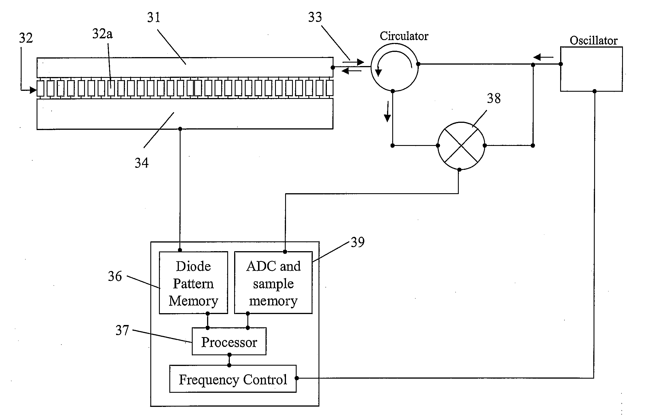
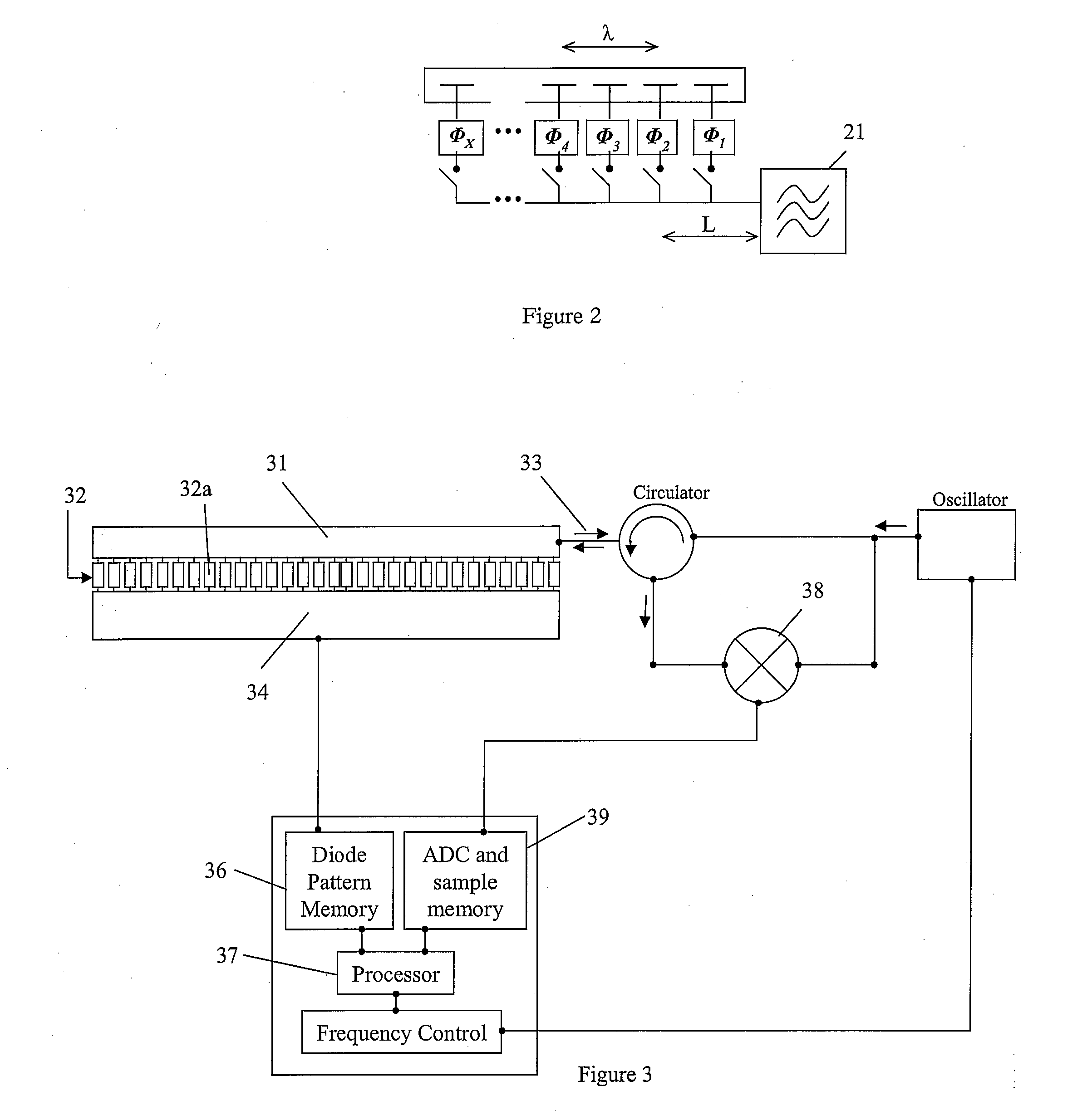
[0045]Shown in FIG. 3 is a mono-static phased array, at its heart is a rod 31 like element which functions as a waveguide of the kind disclosed in U.S. Pat. No. 5,982,334. Coupled to the rod 31 is a switching means 32 which can be conceptually considered to comprise a set of switches. Each switch can be operated between a high gain “on” state and “off” state. In the on state, the switch causes a region of the rod to permit radiation to escape from the rod 31 by evanescent switching. This region is referred to as an antenna element within this application, and because it can be turned on or off by the switch it can be considered to be an active antenna element. The switching means 32 co-operates with the rod 31 in such a manner that a series of these evanescent coupling regions are defined along the length of the rod 31 to form a configurable linear antenna array.

[0046]The switching means 32 comprises a semi-conductive slab with a plasma grating, as taught in U.S. Pat. No. 5,982,334 ...


PUM


Abstract

An active antenna array is arranged to activate subsets of switchable elements causing the antenna to form a first beam having a first beam pattern, and later to form a second beam having a second beam pattern of substantially identical far field radiation pattern to the first beam pattern but with different origins. A receiver receives radiation reflected from a target back to the antenna when the antenna is configured with the first beam pattern and then when configured with the second beam pattern, and compares the phase of the radiation received at the receiver when the antenna is configured with the first beam pattern with the phase of the radiation received at the receiver when the antenna is configured with the second beam pattern to provide a phase difference signal. A target locating means determines the angular location of the target from the phase difference signal.

Description

CROSS-REFERENCE TO RELATED APPLICATIONS[0001]This application is a national stage of International Application No. PCT / IB2010 / 000277 filed Feb. 11, 2010, the disclosures of which are incorporated herein by reference, and which claimed priority to Great Britain Patent Application No. 0902314.4 filed Feb. 12, 2009, the disclosures of which are incorporated herein by reference.BACKGROUND OF THE INVENTION[0002]This invention relates to improvements in antenna arrays, such as active slot antennas and the like, which can be configured to produce a set of directional far field radiation patterns suitable for use in determining the angular location of a target.[0003]The use of radar to determine the distance to a target is well known. In a very simple system the time of flight of a signal transmitted from an antenna to a target and returning to the antenna provides an indication of the range of the target. This works well for targets that are very far away, but for close targets the time of...

Claims


Application Information

Patent Timeline
IPC IPC(8): G01S13/06G01S13/58
CPCH01Q1/3233H01Q3/24H01Q3/2605G01S13/48G01S7/28G01S13/4463H01Q21/08
Inventor BLACHFORD, RICHARD
Owner TRW AUTOMOTIVE US LLC
Why Eureka
Try Eureka