Liquid crystal display device

a liquid crystal display and display device technology, applied in the field of liquid crystal display devices, can solve the problems of reducing the reuse efficiency of light reflected by the back side of the liquid crystal panel, and achieve the effects of increasing the reuse efficiency of light, reducing power consumption, and increasing brightness

Active Publication Date: 2012-03-22
JAPAN DISPLAY INC
View PDF6 Cites 15 Cited by
  • Summary
  • Abstract
  • Description
  • Claims
  • Application Information

AI Technical Summary

Benefits of technology

[0019]In the liquid crystal display device according to the present invention, the linearly polarized light in the absorption axis direction that is reflected on the reflective polarizing plate and returned in the direction of the backlight is scattered on the surface of the concave-convex portion by the difference in the refractive index between the isotropic material part and the refractive index anisotropic sheet. As a result, the scattered light is depolarized. On the other hand, the linearly polarized light in the transmission axis direction is transmitted through the polarizing plate on the back side of the liquid crystal panel, and then reflected in the direction of the backlight by the back side of the liquid crystal panel such as the wiring of the liquid crystal panel. In this case, the linearly polarized light is not scattered because the refractive index in the transmission axis direction of the refractive index anisotropic sheet is the same as the refractive index of the isotropic material part. Thus, the linearly polarized light is transmitted with the polarization kept in the transmission axis direction through the anisotropic diffusion sheet. This increases the reuse efficiency of the light reflected on the back side of the liquid crystal panel. As a result, it is possible to increase the brightness while reducing power consumption.

Problems solved by technology

However, in the liquid crystal display device including the reflective polarizing plate of JP-A No. 298634 / 2007, there is no consideration of the linearly polarized light that is transmitted through the back-side polarizing plate, and then reflected in the direction of the backlight by the back side of the liquid crystal panel, such as the wiring of the liquid crystal panel.
This reduces the reuse efficiency of the light reflected by the back side of the liquid crystal panel.

Method used


Image

  • Liquid crystal display device
  • Liquid crystal display device
  • Liquid crystal display device

Examples


first embodiment

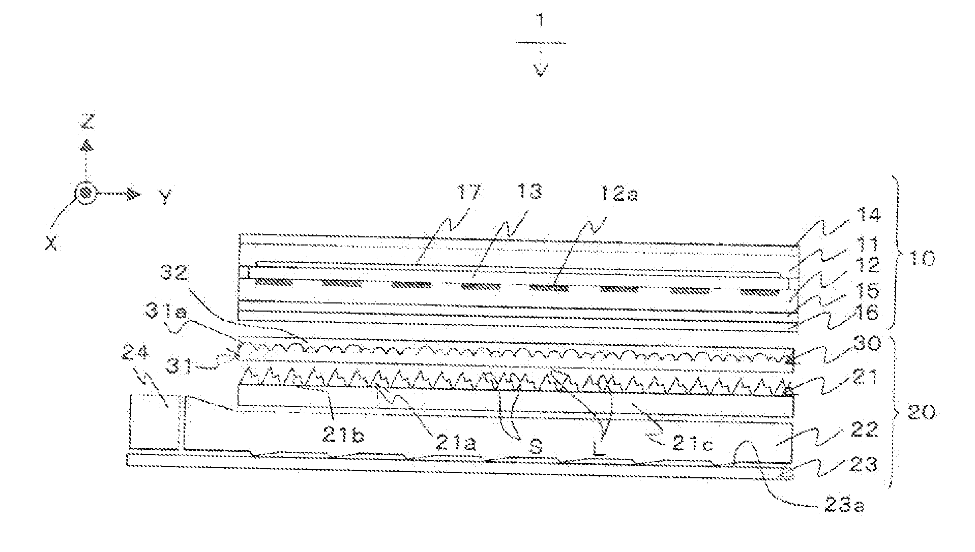
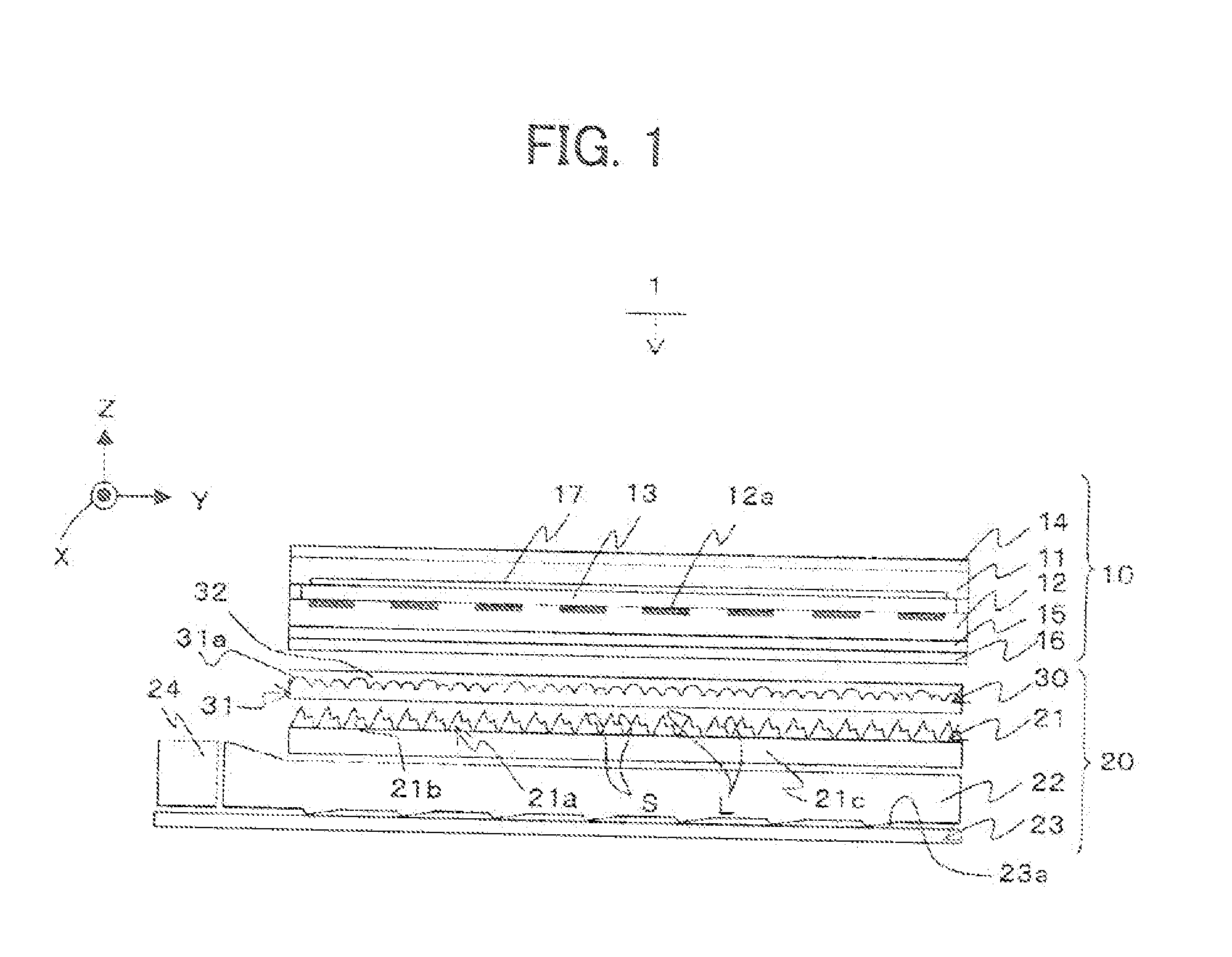
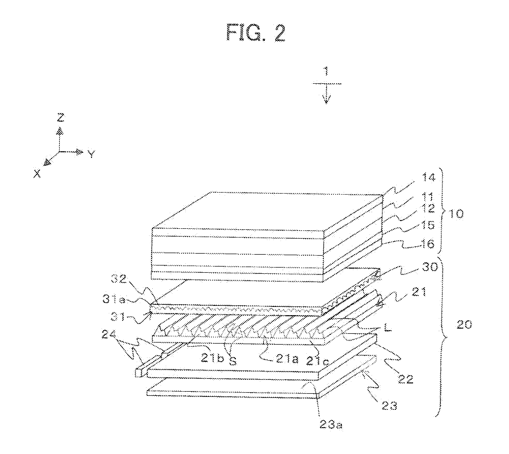
[0032]FIG. 1 is a schematic diagram of the general configuration of a liquid crystal display device 1 according to a first embodiment of the present invention. FIG. 2 is a perspective view of the liquid crystal display device 1 shown in FIG. 1. FIG. 3 is a front view of a refractive index anisotropic sheet 31 shown in FIG. 1. FIG. 4 is a diagram showing a linearly polarized light R2 transmitted with the polarization kept in an anisotropic diffusion sheet 30, as well as a linearly polarized light R3 that is scattered and depolarized. Note that in FIGS. 1 to 4, the transmission axis direction of a back-side polarizing plate 15 is defined as the Y axis, the absorption axis direction of the back-side polarizing plate 15 is defined as the X axis, and the normal direction on the XY axis plane is defined as the Z axis.

[0033]The liquid crystal display device 1 is an active matrix method. The liquid crystal display device 1 includes a liquid crystal panel 10, a backlight 20, and a control un...

second embodiment

[0071]Next, a liquid crystal display device of a second embodiment according to the present invention will be described. FIG. 9 is a schematic diagram of the general configuration of a liquid crystal display device 2 according to the second embodiment of the present invention. FIG. 10 is a diagram showing the linearly polarized light R2 that is transmitted with the polarization kept in an anisotropic diffusion sheet 70, and the linearly polarized Light R3 that is diffracted and depolarized.

[0072]In the liquid crystal display device 1 according to the first embodiment of the present invention, the light is scattered by the concave-convex portion 31a. As a result, the scattered light is depolarized. However, in the liquid crystal display device 2, the light is diffracted and then depolarized.

[0073]The liquid crystal display device 2 has the anisotropic diffusion sheet 70 in place of the anisotropic diffusion sheet 30 used in the liquid crystal display device 1 of the first embodiment....


PUM

PropertyMeasurementUnit
depolarization ratioaaaaaaaaaa
anisotropicaaaaaaaaaa
anisotropic diffusionaaaaaaaaaa

Abstract

The backlight has an anisotropic diffusion sheet disposed between the reflective polarizing plate and the optical path converter. The anisotropic diffusion sheet includes a refractive index anisotropic diffusion sheet stretched in an absorption axis direction in which a concave-convex portion is formed on a surface of the reflective polarized plate, and an isotropic material part laminated on a surface of the concave-convex part. The isotropic material part has an isotropic reflective index. The refractive index of the isotropic material part is the same as the refractive index in the transmission axis direction perpendicular to a stretching direction of the refractive index anisotropic sheet.

Description

CLAIM OF PRIORITY[0001]The present application claims priority from Japanese Patent Application JP 2010-209028 filed on Sep. 17, 2010, the content of which is hereby incorporated by reference into this application.FIELD OF THE INVENTION[0002]The present invention relates to a liquid crystal display device having a backlight for emitting light from the back side of a liquid crystal panel.BACKGROUND OF THE INVENTION[0003]In the conventional liquid crystal display device including a backlight for emitting light from the back side of a liquid crystal panel, an image is displayed on the liquid crystal panel by the light emitted from the backlight. In such a liquid crystal display device, the liquid crystal panel includes a pair of transparent substrates, a liquid crystal material interposed between the pair of transparent substrates, and a pair of polarizing plates provided on the front side and back side of the liquid crystal panel. The polarization state of the light incident to the li...

Claims


Application Information

Patent Timeline
Patent Type & Authority Applications(United States)
IPC IPC(8): G02F1/1335
CPCG02B5/0257G02F1/13363G02F1/133606G02F1/133536
Inventor SUGITA, TATSUYAADACHI, MASAYA
Owner JAPAN DISPLAY INC
Why Eureka
Try Eureka