Device for distributing charge material in a shaft furnance

a charge material and shaft furnace technology, applied in the direction of charge manipulation, gearing, furnaces, etc., can solve the problems of a significant part of the total cost of the device, reduce the intervention time for continued operation, increase positioning flexibility and tolerance, and minimize the effect of intervention tim

Inactive Publication Date: 2012-03-22
PAUL WURTH SA
View PDF8 Cites 12 Cited by
  • Summary
  • Abstract
  • Description
  • Claims
  • Application Information

AI Technical Summary

Benefits of technology

[0015]In order to increase positioning flexibility and tolerance regarding minor misplacement or improper orientation, wherein the first shaft of the differential is preferably coupled to the connecting shaft of the first casing by means of a homokinetic universal joint arrangement. In addition or alternatively, the second shaft can be coupled to the connecting shaft of the second casing by means of a homokinetic universal joint arrangement. Preferably, the homokinetic universal joint arrangement comprises a double Cardan shaft with length compensation, e.g. through a length-extensible intermediate shaft. In order to further increase tolerance in orientation between the shafts, each of the two Cardan joints of the Cardan shaft is preferably a centered double Cardan joint.
[0016]In a preferred configuration, which minimizes the intervention time for continued operation in case of removal of the third casing, the main rotation drive is mounted on the first casing and the first casing and the second casing are arranged on the main housing so that their connecting shafts are aligned. In this configuration, the third casing can simply be replaced by a rigid torque transmission link.

Problems solved by technology

Since it is custom made, it represents a significant part of the total cost of the device.

Method used


Image

  • Device for distributing charge material in a shaft furnance
  • Device for distributing charge material in a shaft furnance
  • Device for distributing charge material in a shaft furnance

Examples


first embodiment

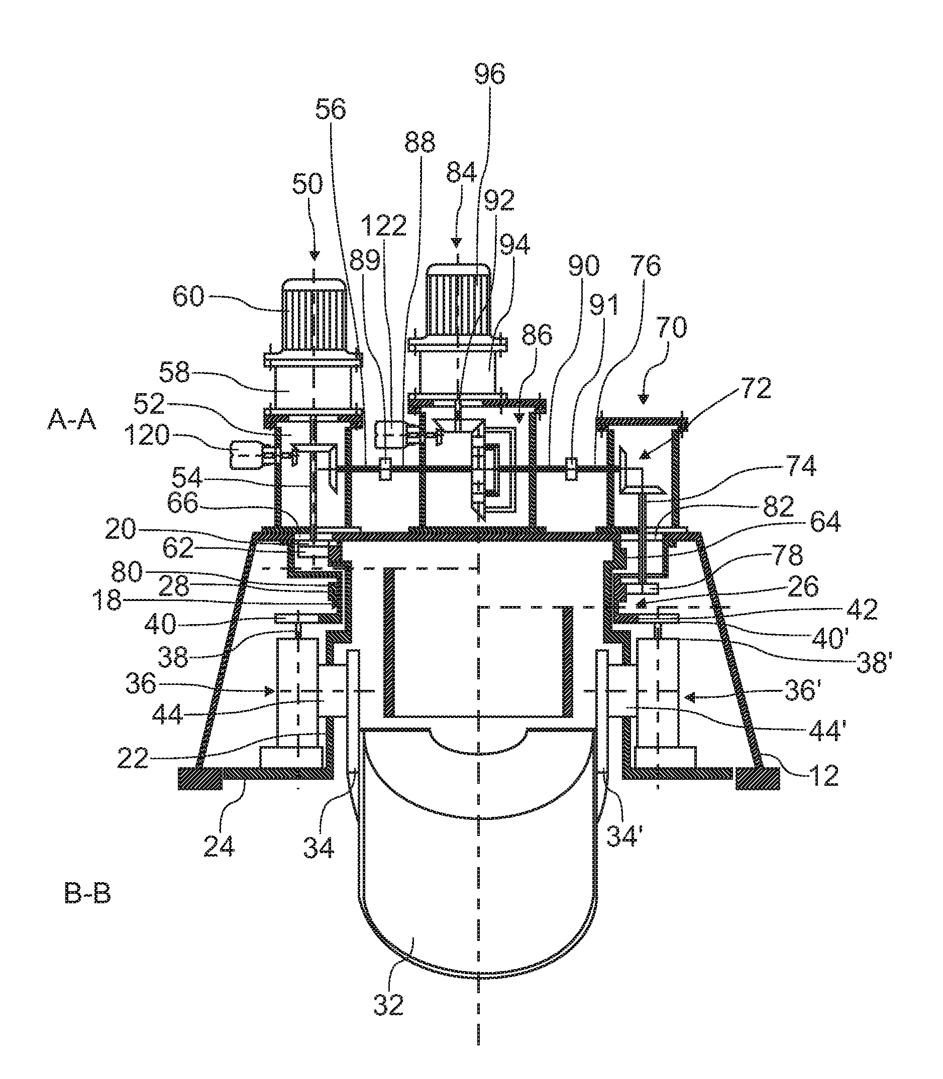
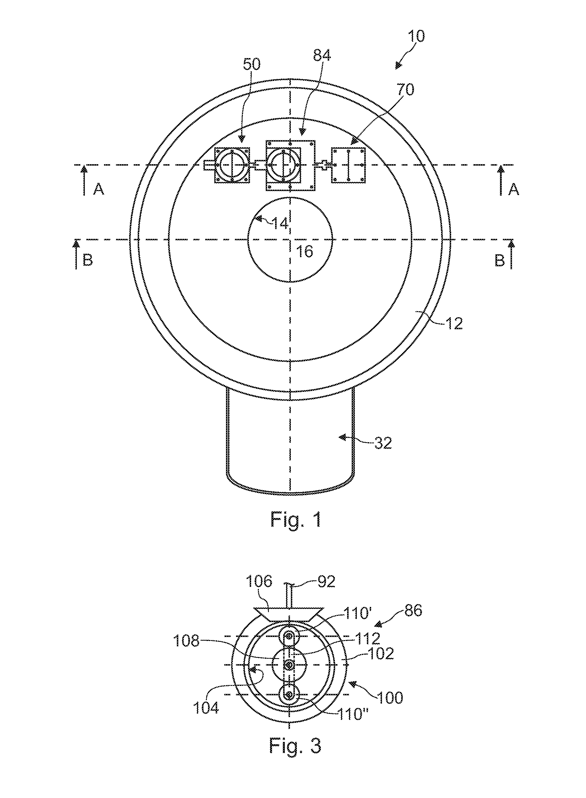
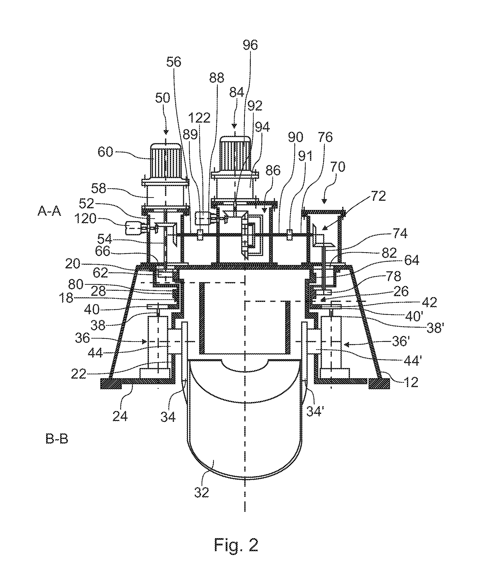
[0035]FIGS. 1-2 illustrate a device 10 for distributing bulk charge material (“burden”) into a shaft furnace, especially onto the stockline of a blast furnace. The device 10 is designed to be part of a charging installation, which is not shown in its entirety. It comprises a main housing 12 to be arranged on the furnace throat and which includes a fixed feeding spout 14 that defines a vertical feeding channel 16. A suspension rotor 18 is suspended inside the main housing 12 by means of a first large-diameter annular roller bearing 20 to be rotatable about a substantially vertical rotation axis. The suspension rotor 18 comprises a generally cylindrical body provided at its lower in with a disk-shaped horizontal protection flange 24, which forms a screen between the interior of the main housing 12 and the interior of the furnace. A second rotor, hereinafter called adjustment rotor 26, surrounds the suspension rotor 18 and is suspended inside the main housing 12 by means of a second la...

second embodiment

[0045]Turning now to FIGS. 4-5, a distribution device 210 will be described hereinafter. Features in the lower part of FIG. 5, which are essentially identical to those described with respect to FIG. 2, are identified by identical reference signs and will not be described again.

[0046]The charging device 210 of FIGS. 4-5 comprises a third casing 284 that is spaced apart from the first casing 250 and the second casing 270. The third casing 284 is arranged on the main housing 12 approximately on the median plane between the casings 250, 270 and laterally offset away from the furnace central axis, i.e. the rotation axis of the rotors 18, 26. As opposed to the preceding embodiment, in the charging device 210 of FIGS. 4-5, the first and second shafts 288, 290, which are connected to the differential 286 in the third casing 284, are thus not aligned with the connecting shafts 256, 276 of the first and second casings 250, 270.

[0047]To bridge the offset, the first and second shafts 288, 290 a...

third embodiment

[0058]With respect to FIGS. 1-3 and FIG. 4-5, the embodiment of FIGS. 10-11 generally corresponds to a combination employing a single homokinetic universal joint arrangement as shown in FIGS. 4-5, e.g. between the first and third casings 250; 284, and a simpler flexible compensating coupling as shown in FIG. 2, e.g. between the second and third casings 270, 284. FIGS. 10-11 schematically illustrate a distribution device 310 according to such a

[0059]In the distribution device 310 of FIGS. 10-11, the connecting shaft 356 of the first casing 350 is coupled to the first shaft 388 of the differential 786, which is arranged in the separate third casing 384, by means of a double Cardan shaft 385, which is configured as described above. The connecting shaft 376 of the second casing 370 however is connected to the second shaft 390 of the differential 786 by means of a simpler compensating coupling 399, e.g. a jaw coupling, an Oldham coupling, a flexible disk coupling or a gear coupling, for ...


PUM

PropertyMeasurementUnit
speedaaaaaaaaaa
angleaaaaaaaaaa
lengthaaaaaaaaaa

Abstract

A device (10) for distributing charge material into a shaft furnace comprises a main housing (12), a distribution chute, a suspension rotor (18) and an adjustment rotor (26), which are rotatable about a substantially vertical axis. The chute (32) is suspended to the suspension rotor (18) to rotate therewith for circumferential distribution of charge material and adjustable in orientation through the adjustment rotor (26) for radial distribution of charge material. A differential gear (86) interconnects the suspension rotor (18) and the adjustment rotor (26) and is configured to transmit to the adjustment rotor the same speed of rotation that is imparted to the suspension rotor by a main rotation drive (60) unless an adjustment drive (96) imparts, through the differential gear, a differential rotation to the adjustment rotor. According to the invention, the device includes: a first casing (50) arranged on the main housing (12) and enclosing an angular transmission (52) between a substantially vertical output shaft (54), which protrudes from the first casing (50) into the main housing and is connected to a gearwheel (62) that meshes with a first gear ring (64) on the suspension rotor (18), and a connecting shaft (56), which protrudes from the first casing (50) at an angle, in particular perpendicularly, with respect to the output shaft (54); a second casing (70) arranged on the main housing (12) and enclosing an angular transmission (72) between a substantially vertical output shaft (74), which protrudes from the second casing (70) into the main housing and is connected to a gearwheel (78) that meshes with a second gear ring (80) on the adjustment rotor (26), and a connecting shaft (76(, which protrudes from the second casing (70) at an angle, in particular perpendicularly, with respect to the output shaft (74); a third casing (84) that is spaced apart from the first and second casings (50, 70) and encloses the differential gear (86), the differential gear being connected to a first shaft (88), which is coupled to the connecting shaft (56) of the first casing (50), and to a second shaft (90), which is coupled to the connecting shaft (76) of the second casing (70).

Description

TECHNICAL FIELD[0001]The present invention generally relates to a charging installation for a shaft furnace and in particular to a device for distributing charge material in the furnace. More specifically, the invention relates to the type of device that is equipped with a chute for circumferential and radial distribution of the charge material.BRIEF DESCRIPTION OF RELATED ART[0002]A device of this type is known from U.S. Pat. No. 3,693,812. The device according to U.S. Pat. No. 3,693,812 has a suspension rotor and a chute adjustment rotor that are supported in a main housing so as to be rotatable about a substantially vertical rotation axis. The chute is suspended to the suspension rotor so that it rotates with the latter for circumferential distribution of charge material. Furthermore, in the device according to U.S. Pat. No. 3,693,812, the chute is suspended to be pivotally adjustable about a substantially horizontal axis for radial distribution of charge material. The suspension...

Claims


Application Information

Patent Timeline
Patent Type & Authority Applications(United States)
IPC IPC(8): F27B1/20F27D3/00C21B7/20
CPCC21B7/20F27D3/10F27B1/20F16H37/0806C21B7/205
Inventor THILLEN, GUYLONARDI, EMILEHAUSEMER, LIONELTHIX, CHRISTIAN BENOIT
Owner PAUL WURTH SA
Why Eureka
Try Eureka