Method for producing metal elements, in particular sealing elements

a technology of sealing elements and metal elements, which is applied in the field of sealing elements, can solve the problems of high material expenditure, high cost, and high cost of such materials, which have a wide variety of sealing properties, and achieve the effect of minimizing material loss

Inactive Publication Date: 2012-03-22
FEDERAL MOGUL SEALING SYST
View PDF2 Cites 12 Cited by
  • Summary
  • Abstract
  • Description
  • Claims
  • Application Information

AI Technical Summary

Benefits of technology

[0014]To begin with, sheet metal strips or foil strips having defined lengths and widths are generated from a base body in the form of a foil, or sheet metal having a predefinable thickness, for example by laser cutting, fine blanking or similar methods. The essential aspect here is that the mutually opposing edges, which are subsequently welded to each other, are free of burrs. It may be helpful in some instances not to weld straight ends to each other, but rather to employ a zigzag or wave contour so as to achieve better joining of the edge regions and additionally provide the weld seam with further advantageous properties (for example, a certain rigidity or the like).
[0017]Segments or rings are cut off the contoured tube (end). Suitable methods for this purpose include roller cutting, laser cutting, water jet cutting or the like. Preferably, roller cutting is employed because in this way either no loss of material is incurred at all, or the loss of material is minimized, and additionally the resulting edges of the ring element can still be provided with a special edge contour.

Problems solved by technology

However, to date, they have been die-cut from sheet metals, resulting in high material expenditure and high costs.
The costs for such materials, which have a wide variety of sealing properties, are at times significant, especially when large, narrow rings must be die-cut from sheet metal.

Method used


Image

  • Method for producing metal elements, in particular sealing elements
  • Method for producing metal elements, in particular sealing elements
  • Method for producing metal elements, in particular sealing elements

Examples


Embodiment Construction

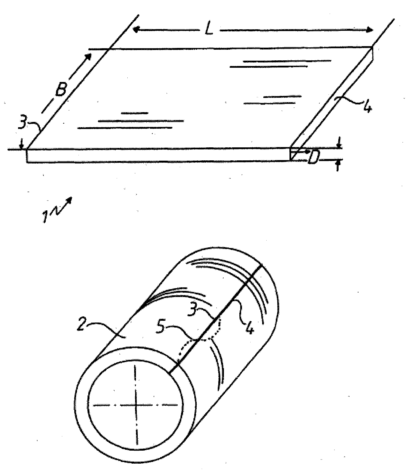
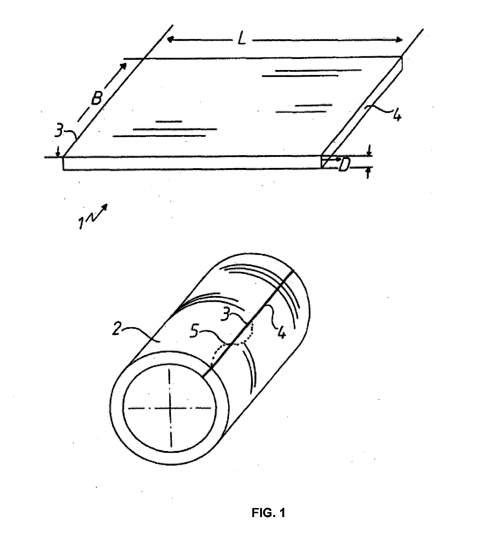
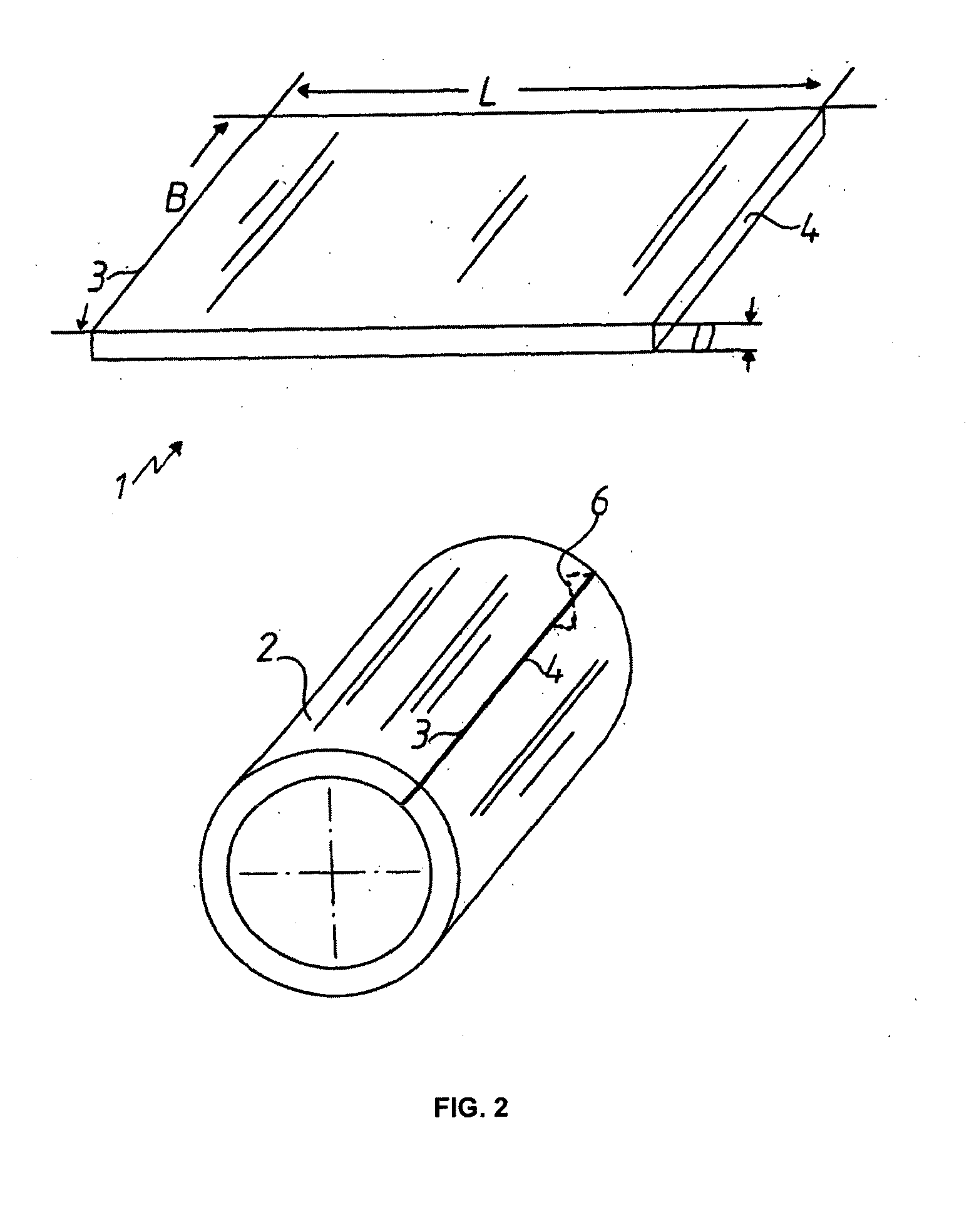
[0026]FIGS. 1 to 3 show sheet metal strips or foil strips 1, which have predefined lengths L, widths B, and thicknesses D, and which have already been cut out from a base body (not shown). So as to generate various properties in the end product, sheet metal strips or foil strips 1 having different rolling directions can be employed. The respective sheet metal strip or foil strip 1 is formed so as to obtain the respective tube 2 shown in FIGS. 1 to 3. The end regions 3, 4 of the tubes 2 shown in FIGS. 1 and 2 are connected to each other over the entire length by bonding, or by non-positive or positive joining techniques, and in this example, they are connected to each other by welding. Profiles of the end regions 3, 4, which serve to produce defined properties in the end product are indicated only by dotted lines.

[0027]FIG. 4 is a schematic diagram of the tube 2 shown in FIG. 1 or 2. Defined contours 9 are impressed in the outer circumferential surface 8 of the tube 2 using hydroform...


PUM

PropertyMeasurementUnit
lengthaaaaaaaaaa
combustion pressuresaaaaaaaaaa
combustion temperaturesaaaaaaaaaa

Abstract

A method for producing metallic elements, and more particularly sealing elements, wherein a sheet metal strip or a foil strip having a predefinable length, width, and thickness is generated and the sheet metal strip or foil strip is formed to obtain a tube, the mutually opposing end regions or parts, or the entire contact surface of the sheet metal strip or foil strip, are connected to each other non-positively or positively or by bonding, or combinations thereof, and the entire length of the tube, or portions thereof, is subjected to a mechanical shape-forming process so that predefinable contours are introduced into the outer or inner circumferential surface of the tube in defined locations by a means, and the tube is divided into an appropriate number of individual elements, and in particular sealing elements, especially sealing rings for turbochargers.

Description

BACKGROUND OF THE INVENTION[0001]The invention relates to a method for producing metallic elements, and more particularly sealing elements.[0002]Such elements, notably sealing elements, are used quite frequently as sealing rings for turbochargers, stopper rings, borders, support disks or washers.[0003]Such annular metallic elements have a broad range of applications. For example, metallic annular sealing rings, which typically have either a C-shaped or a V-shaped cross-section, are used for turbochargers. Until now, such sealing elements have been used only rarely as exhaust system flange gaskets. Stopper rings are used in production cylinder head gaskets. However, to date, they have been die-cut from sheet metals, resulting in high material expenditure and high costs.[0004]Given the fact that modern power units or internal combustion engines place ever greater demands on the sealing technology, because both combustion pressures and combustion temperatures are steadily rising, incre...

Claims


Application Information

Patent Timeline
Patent Type & Authority Applications(United States)
IPC IPC(8): F04D29/08B21D43/28B26D1/00B21B23/00
CPCF16J15/0887B21D53/20Y10T83/04
Inventor PREHN, ROLF
Owner FEDERAL MOGUL SEALING SYST
Why Eureka
Try Eureka