However, the body still has fluid that collects in the open space.
There is a recognized problem with conventional wound drain technology, which is directly related to the nature of the
wound healing process itself.
As a result, current wound drain technology is not effective at adequately clearing wound voids.
Concurrently, current drains are ineffective at formally closing down larger dead spaces, and can only manage small amounts of fluid directly around the drain itself.
Finally, conventional wound drains provide non-uniform blood and fluid removal with low inconsistent suction pressure, often with long drain duration and the potential of infection.
The problem with these devices is that they may become plugged by blood clots carried by the
wound fluid, or may be overwhelmed by the fluid generated in the space, or may have such low continuous pressure that they are ineffective at closing the internal space down.
Further, although they may, when not plugged, drain fluid, fluid drainage is limited to fluid directly around the drain itself.
As a result, current drains again, at best, do not effectively clear all of the fluid in the space and, more importantly, they do not clear enough fluid to effectively seal down and close off the
dead space.
Conventional VAC devices, however, are only approved and used for external wounds.
Conventional VAC devices are not approved or used for
internal wounds or operative sites, and may create bleeding upon withdraw and leave particulate matter from the foam inside the wound base.
Current wound drain devices assemblies at times do not remove a substantial amount of fluid from within a wound and have other performance issues.
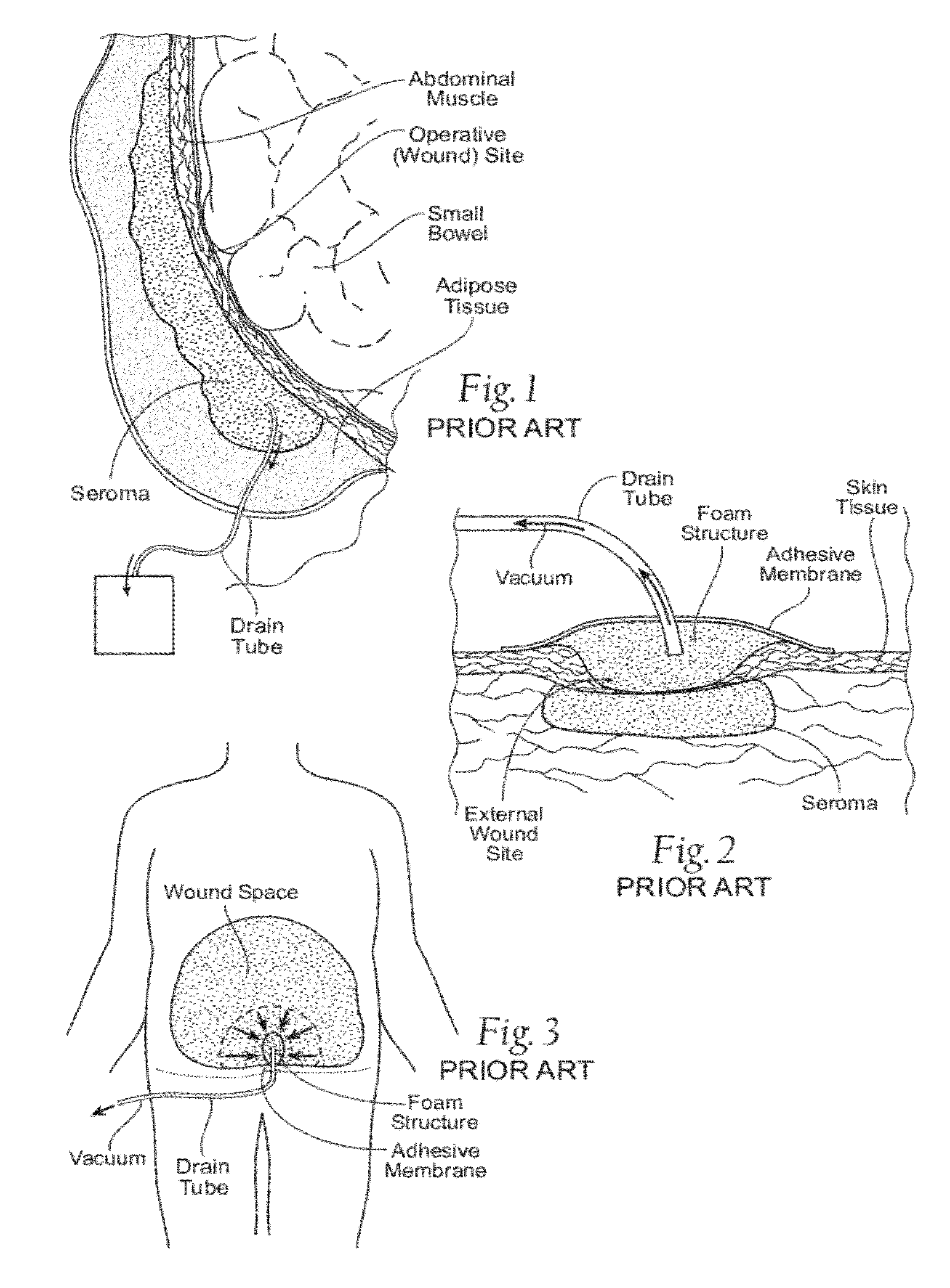
For example, external VAC devices clear fluid directly around external wounds (as FIG. 3 shows), and they are limited to the application to external wounds only.
Furthermore, the clinical use of external VAC devices may not make
wound drainage more cost-effective, clinician-friendly, and patient-friendly.
Removal of the foam structures in the presence of granulating tissue and the force of pressure on the wound
bed that this removal can cause pain or discomfort.
Furthermore, the multiple steps of the conventional external VAC procedure—removing the
adhesive membrane, then removing the old foam structures, then inserting the new foam structures, and then reapplying the
adhesive member along the entire periphery of the wound—are exacting, tedious and
time consuming.
They only prolong pain or discomfort, and cause further disruption to the patient, and also demand dedicated
nursing time and resources.
Obtaining such a seal can be difficult, particularly in
body regions where the surrounding
skin is tortuous, and / or mucosal and / or moist.
Furthermore, prolonged wearing of wet dressings can cause further breakdown and maceration of the surrounding
skin thereby increasing the
wound size.
This can cause further discomfort to the patient, and the
exudate can often be offensive in
odor and color causing further morbidity to the patient.
This may, in turn, require more numerous dressing changes and re-padding throughout the day, which is disruptive to the patient and costly both in terms of
nursing time and resources.
Such complications result in a significant amount of lost income to patients, as well as expenses to insurers and physicians who have to care for these patients that require serial drainage.
The inability to prevent or treatment seromas that form in closed interior wounds is a problem that has persisted in the field of elective
surgery since the beginning of surgery, and has been documented in the surgical literature for all specialties over the last fifty years.
Seromas and abnormal fluid collection are so common, that physicians and surgeons will acknowledge that seromas are, unfortunately, an expected part of wound healing following surgery.

