

Mixing system in an exhaust gas mixing chamber
- Summary
- Abstract
- Description
- Claims
- Application Information
AI Technical Summary
Benefits of technology
Problems solved by technology
Method used
Image

Examples
first embodiment
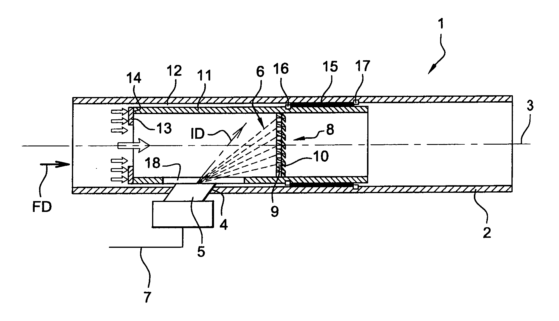
[0042]the invention will now be described with reference to FIGS. 1 and 2.
[0043]According to this embodiment, there is provided an evaporating device comprising, in addition to its principal evaporating portion 9, an inner duct 11 arranged substantially coaxially inside the pipe 2. The inner duct 11 has an outside diameter slightly smaller than the inside diameter of pipe 2, so that a substantially cylindrical space 12 is provided between the inner duct 11 and the pipe 2 through which a small amount of the exhaust gases can flow.
[0044]The inner duct 11 has an annular collar 13 projecting inwardly from the upstream edge 14 of said inner duct 11. The inner duct 11 as well as the annular collar 13 can be made of a thin metal.
[0045]The inner duct 11 is movably bound to the pipe 2 by means of a helical compression spring 15 located in the cylindrical space 12, said spring 15 having its upstream end 16 coupled to the inner duct 11 and its downstream end 17 coupled to the pipe 2. The sprin...
second embodiment
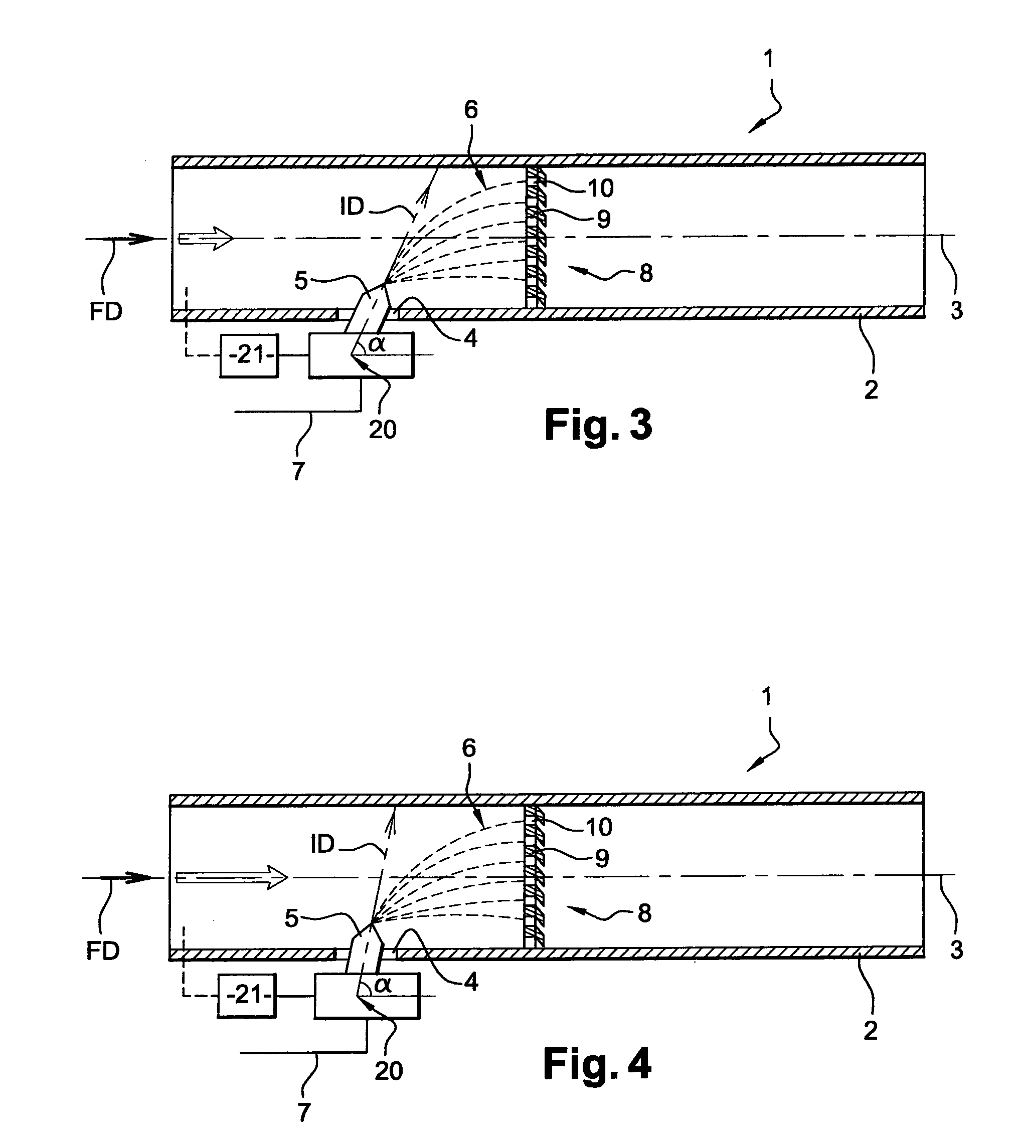
[0050]the invention will now be described with reference to FIGS. 3 and 4.
[0051]According to this embodiment, no inner duct is provided. The evaporating device 8 is fixed inside the pipe 2 and the nozzle 5 can pivot with respect to the pipe 2 so as to inject the fluid along an injection direction ID which is all the more tilted with respect to the pipe axis 3 as the exhaust gases flow rate is high. Indeed, a low flow rate means a smaller deflection of the second fluid spray 6 by the exhaust gases; thus, it is necessary to inject the second fluid according to a less tilted injection direction ID so that the second fluid is directed towards the evaporating device 8.
[0052]The pivoting axis 20 of nozzle 5 is parallel to a plane substantially tangential to the pipe 2 at the injection inlet 4 and which is orthogonal to the pipe axis 3. The angle α between the flow direction FD and the injection direction ID can be adjusted by active control means 21 which may include an actuator. Said act...
PUM
| Property | Measurement | Unit |
|---|---|---|
| Flow rate | aaaaa | aaaaa |
| Electrical conductor | aaaaa | aaaaa |
Abstract
Description
Claims
Application Information