Image Pickup Lens, Image Pickup Device Provided with Image Pickup Lens, and Mobile Terminal Provided with Image Pickup Device

a technology of image pickup and image, which is applied in the direction of instruments, optics, mountings, etc., can solve the problems of large decentration sensitivity, and deterioration of mtf characteristic, so as to reduce the load of the motor of the lens drive mechanism, reduce and reduce the effect of the total length of the image pickup lens

Active Publication Date: 2012-03-29
KONICA MINOLTA OPTO
View PDF6 Cites 41 Cited by
  • Summary
  • Abstract
  • Description
  • Claims
  • Application Information

AI Technical Summary

Benefits of technology

[0030]According to the present invention described in claim 1, the focusing lens group is composed of plural lenses. Therefore, by arranging lenses in the focusing lens group so as to cancel the decentration sensitivities of respective lenses mutually, the decentration sensitivity of the total system of the image pickup lens can be decreased. When the decentration sensitivity of the total system of the image pickup lens is decreased, deterioration of optical properties coming from decentration sensitivities in a process of manufacturing lenses and structural members and a process of assembling lenses and structural members can be controlled. Further, an amount of lens movement for performing image pickup at a close distance becomes small, which shortens the total length of the image pickup lens, forms a space where a lens drive mechanism is arranged at the outer circumference side of the focusing lens group, downsizes the image pickup lens in the radial direction, and downsizes an image pickup device where an image pickup lens is to be mounted. Further, by disposing a lens facing the image pickup element stationarily, a load of a motor of the lens drive mechanism can be reduced.
[0031]When the lens facing the image pickup element is stationarily disposed, the space around the image plane can be enclosed with the lens facing the image pickup element and the image pickup element, which reduces dust adhering around the image plane. Even when dust enters the inside of the image pickup lens, it adheres to a subject-side surface of a stationary lens including the lens facing the image pickup element. Since the dust is located away from the image plane, there is no fear that the optical properties are deteriorated. Further, since the lens facing the image pickup element is not required to be moved in the focusing operation and the lens drive mechanism is not required to be arranged at the outer circumference side of a lens with a large outer diameter, the image pickup apparatus can be downsized in the radial direction.
[0032]According to the invention described in claim 2, by providing at least three lenses as a focusing lens group, the decentration sensitivity of the focusing lens group is reduced and fluctuation of various aberrations caused in a focusing operation is controlled, which makes the optical properties excellent.
[0033]To control the fluctuation of optical properties corresponding to the distance to the subject, it is required to correct various aberrations as much as possible in a movable group. By setting the number of lenses to be three, especially field curvature and astigmatism are corrected in excellent conditions. Preferably, there are arranged a positive lens, negative lens and positive lens, in this order. Such the structure is called as a triplet type and is suitable to correct spherical aberration and distortion, additionally to the above aberrations.
[0034]According to the invention described in claim 3, there is formed a space where the lens drive mechanism is arranged at the outer circumference side of the lens closest to the subject, which downsizes the image pickup device wherein the image pickup lens is mounted.
[0035]According to the invention described in claim 4, when the value of the expression (1) exceeds the upper limit, fluctuation of optical properties caused when image pick up from an infinite distance to close distance is performed is hardly controlled. Further, it makes reduction of decentration sensitivity difficult, and deterioration of optical properties coming from manufacturing errors of lenses and structural components and assembling errors of lenses and structural components becomes significant. On the other hand, when the value becomes lower than the lower limit of the expression (1), power of the focusing lens group becomes weak. Therefore, the movement amount of the focusing lens group for performing image pickup at a close distance becomes large, and the total length of the image pickup lens is hardly shortened. When the expression (1) is satisfied, optical properties is controlled when images are picked up in the range from an infinite distance to a close distance, and the movement amount of the focusing lens group becomes a proper value.

Problems solved by technology

However, to meet the demands, the above prior art employs a focusing operation wherein only the first lens is moved, which significantly deteriorates the MTF characteristic at a large-image-height position on an image plane of the image pickup element (off-axis position), with respect to that at an axial position.
Especially in an image pickup lens with a small Fno, the MTF characteristic is significantly deteriorated.
Accordingly, because only the first lens is moved in the prior art, there was problems that the decentration sensitivity becomes large, optical properties is deteriorated and it is hardly applied to an image pickup lens with a small Fno.

Method used


Image

  • Image Pickup Lens, Image Pickup Device Provided with Image Pickup Lens, and Mobile Terminal Provided with Image Pickup Device
  • Image Pickup Lens, Image Pickup Device Provided with Image Pickup Lens, and Mobile Terminal Provided with Image Pickup Device
  • Image Pickup Lens, Image Pickup Device Provided with Image Pickup Lens, and Mobile Terminal Provided with Image Pickup Device

Examples


first embodiment

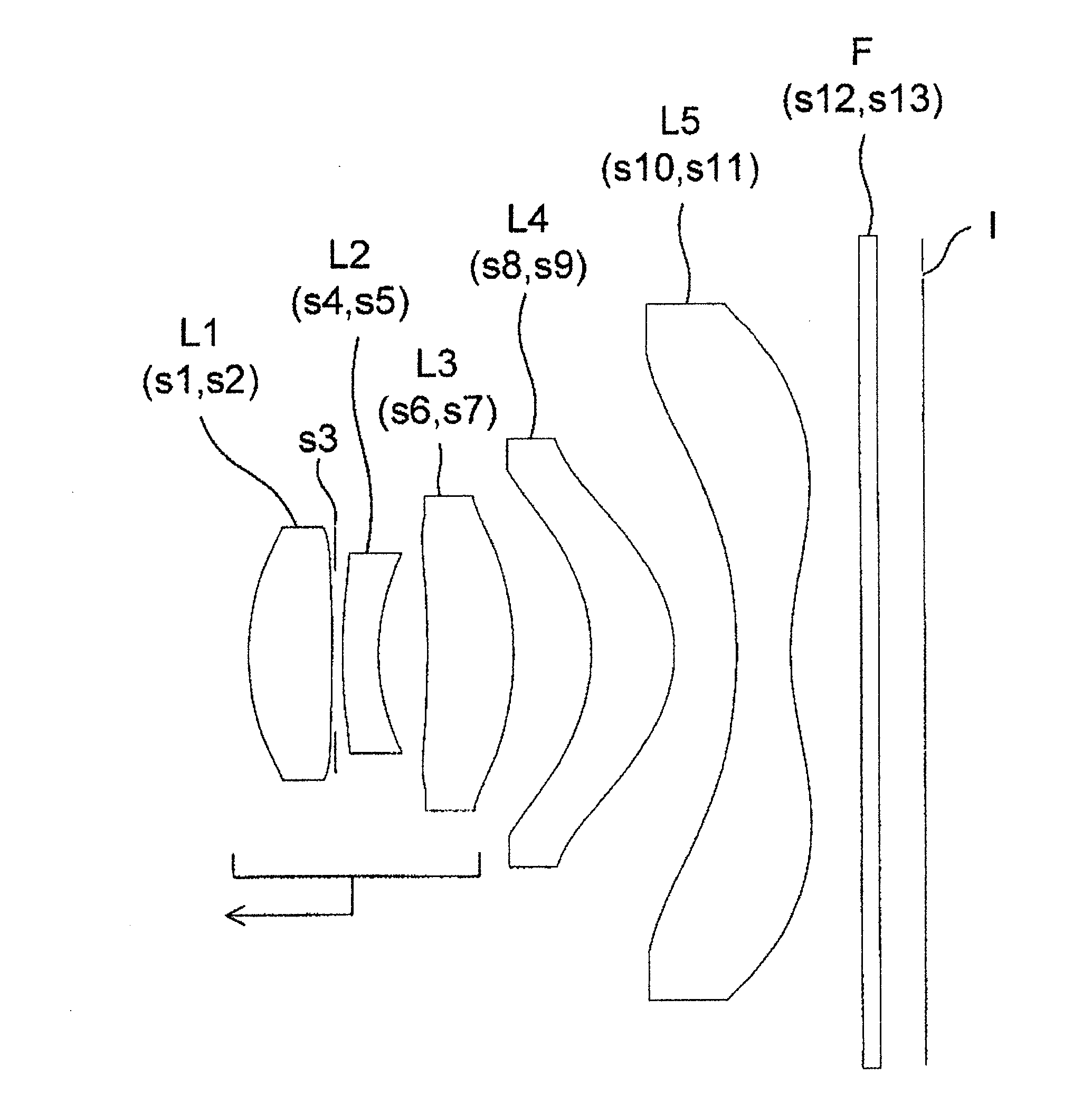
[0091]As shown in FIG. 6, the image pickup lens includes, in order from the subject: first lens L1 in biconcave shape; aperture stop s3; second lens L2 with negative power in meniscus shape whose concave surface faces the image side; third lens L3 with positive power in meniscus shape whose convex surface faces the image side; fourth lens L4 with positive power in meniscus shape whose convex surface faces the image side; and fifth lens L5 in biconcave shape. Each surface of first to fifth lenses L1-L5 has aspheric shape. Especially, an aspheric surface at the image side of fifth lens L5 includes an inflection point at a position excluding the intersection of the optical axis and the aspheric surface. The aspheric surface at the image side of fifth lens L5 has a concaved shape in a paraxial area and has a convex shape in the lens periphery. First to third lenses L1-L3 form a focusing lens group and move to the subject side together as one body when an image is picked up at a close di...

second embodiment

[0092]As shown in FIG. 7, the image pickup lens includes, in order from the subject: first lens L1 with positive power, including a convex surface facing the subject; aperture stop s3; second lens L2 with negative power, including a concave surface facing the subject side; third lens L3 in biconvex shape; fourth lens L4 with negative power in meniscus shape whose concave surface faces the image side; and fifth lens L5 in biconcave shape. Each surface of first to fifth lenses L1-L5 has aspheric shape. Especially, an aspheric surface at the image side of fifth lens L5 includes an inflection point at a position excluding the intersection of the optical axis and the aspheric surface. The aspheric surface at the image side of fifth lens L5 has a concaved shape in a paraxial area and has a convex shape in the lens periphery. As for forth lens L4 and fifth lens L5, when they have weak power and aspheric surfaces, they can be formed to have positive power. First to fourth lenses L1-L4 form ...

third embodiment

[0093]As shown in FIG. 8, the image pickup lens includes, in order from the subject first lens L1 in biconvex shape; aperture stop s3; second lens L2 with negative power in a meniscus shape whose concave surface faces the image side; third lens L3 with positive power in a meniscus shape whose convex surface faces the image side; fourth lens L4 with positive power in meniscus shape whose convex surface faces the image side; and fifth lens L5 in biconcave shape. Each surface of first to fifth lenses L1-L5 has aspheric shape. Especially, an aspheric surface at the image side of fifth lens L5 includes an inflection point at a position excluding the intersection of the optical axis and the aspheric surface. The aspheric surface at the image side of fifth lens L5 has a concaved shape in a paraxial area and has a convex shape in the lens periphery. As for third lens L3, when it has relatively weak power and an aspheric surface, it can be formed to have negative power. First to third lenses...


PUM


Abstract

Provided is an image pickup lens that forms an image on an image pickup element with light from a subject. In the image pickup lens, a lens that is disposed on an image pickup element side is fixed in position, and a focusing lens group having a plurality of lenses including a lens closest to the subject is moved in an optical axis direction, thereby performing focusing.

Description

TECHNICAL FIELD[0001]The present invention relates to an image pickup lens which can guide light to an image pickup element, an image pickup device provided with the image pickup element and a mobile terminal provided with the image pickup device. Especially, the present invention relates to an image pickup lens which can perform a focusing operation, an image pickup device provided with the image pickup element, and a mobile terminal provided with the image pickup device.BACKGROUND ART[0002]Until now, a small and thin image pickup device has become mounted on a mobile terminal such as a cell phone and a PDA (Personal Digital Assistant). Thereby, not only sound information, but also image information can be mutually transmitted to / from a remote place. As an image pickup element for use in such the image pickup device, there are used CCD (Charge Coupled Device) type image sensor and CMOS (Complementary Metal-Oxide Semiconductor) type image sensor. In recent years, demands for adoptin...

Claims


Application Information

Patent Timeline
Patent Type & Authority Applications(United States)
IPC IPC(8): G02B13/18G02B9/60G02B7/04
CPCG02B13/003G02B13/18G02B13/02G02B13/0045
Inventor KONISHI, HIROTOSHIWAKIMURA, TAIZOONISHI, SATOSHIMATSUSAKA, KENJIMORITA, MITSUHIKOSANO, EIGOTANAKA, HIROAKI
Owner KONICA MINOLTA OPTO
Why Eureka
Try Eureka