
Epistem genedrive

a technology of epistem and gene drive, which is applied in the direction of specific use bioreactors/fermenters, enzyme production/based bioreactors, biomass after-treatment, etc., can solve problems such as reducing efficiency, and achieve the effect of small footprint for the cycler

Active Publication Date: 2012-03-29
EPISTEM
View PDF5 Cites 3 Cited by
  • Summary
  • Abstract
  • Description
  • Claims
  • Application Information

AI Technical Summary

Benefits of technology

[0014]A thermal cycler according to the present invention separates the heating and cooling functions, allowing each to be optimised for the desired function. Further, the use of separate heater and cooler elements means that the thermal mass of the heat sink need not influence the performance of the Peltier and the efficiency of heating and cooling the sample block. In addition, a conventional heating element, for example an electrical resistance heating element, is in general more efficient than a Peltier-type element used for both heating and cooling; the Peltier-type element is more efficient when used for cooling only or when heating only.
[0030]The computer processor may be mounted on a substrate, such as a circuit board or a PCB. In preferred embodiments of the invention, the remaining components of the cycler—for example, the Peltier-type element, the heater, the sample block, and the heat sink and pipe—are secured to the substrate. For example, the components may be bolted to the substrate. This allows for ease of construction and assembly, and permits a smaller footprint for the cycler. Of course, not all of the components need be secured directly to the substrate; some of the components may be secured to others (for example, the heater may be secured to the substrate, with the sample block secured to the heater and the Peltier element secured to the sample block). A casing may enclose the substrate and the remaining components.

Problems solved by technology

This conventional arrangement means that there is no position in which a non-Peltier-type heater may be conveniently located, other than between the sample block and the Peltier element, which would further reduce efficiency due to the need to cool through the heater.

Method used


Image

  • Epistem genedrive
  • Epistem genedrive
  • Epistem genedrive

Examples


Embodiment Construction

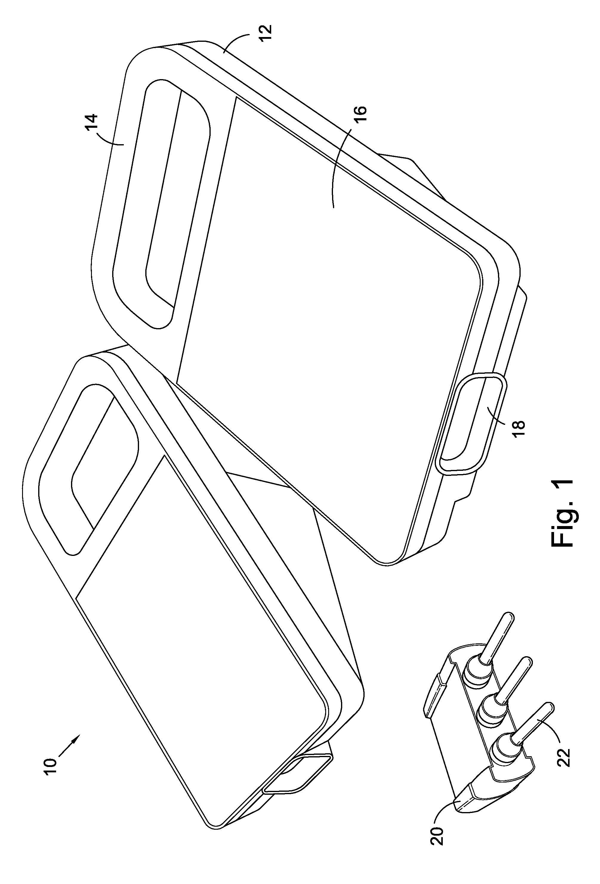
[0036]Referring first of all to FIG. 1, this shows an exterior view of a thermal cycler in accordance with the present invention. The cycler 10 includes an outer casing 12 formed with a carrying handle 14. The upper surface of the casing 12 is provided with a touchscreen interface 16 allowing the user to operate the cycler. The front of the casing provides an opening 18 into which can be inserted a sample holder 20, which includes (in this embodiment) three sample tubes 22 of thin-walled plastic.

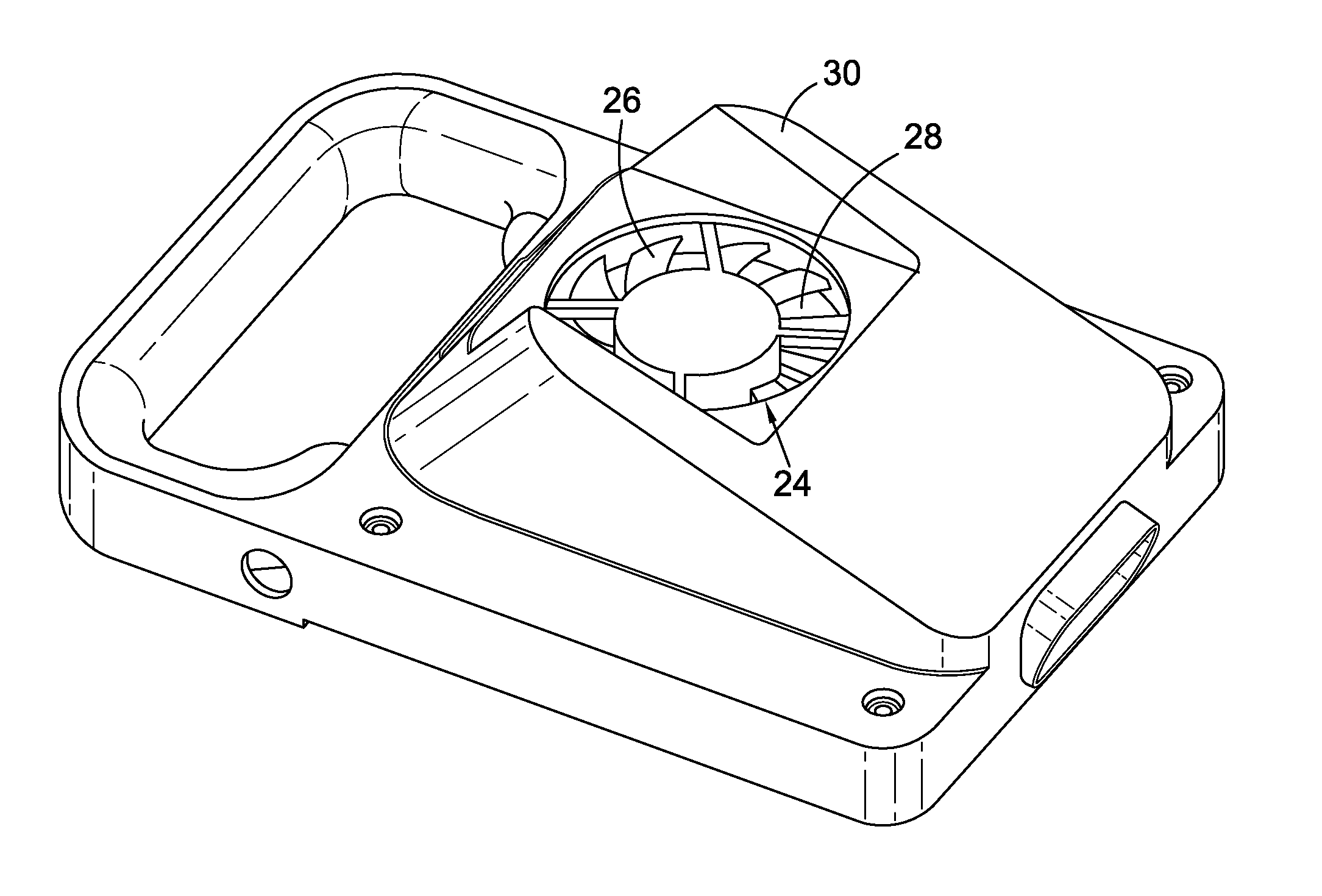
[0037]The underside of the cycler 10 is shown in FIG. 2. The outer casing includes an opening 24 within which is mounted a cooling fan 26 which is adjacent a heat sink 28. The casing is formed with supports 30 which raise the fan 26 off the benchtop, allowing air to circulate.

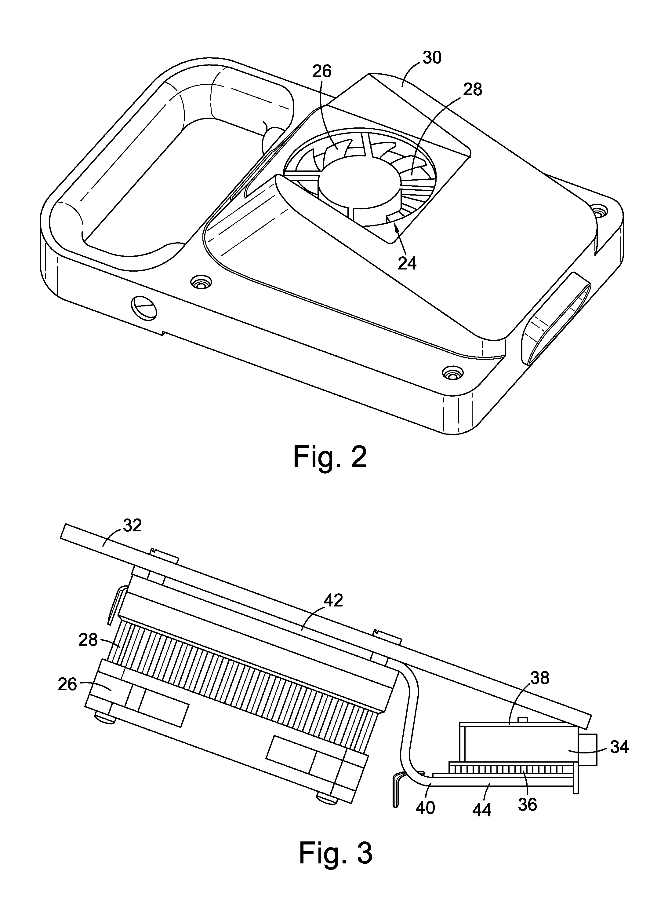
[0038]The internal architecture of the cycler 10 is shown in FIG. 3. The outer casing 12 is not shown in this figure. A PCB substrate 32 is provided, on which are mounted the various electronic components needed to cont...


PUM


Abstract

We describe a thermal cycler comprising a Peltier-type thermoelectric element used for cooling a sample block, and a non-Peltier-type heating device for heating the sample block. The cycler also includes a heat sink connected to the Peltier-type element by a heat pipe, which permits thermal energy to transfer from the Peltier-type element to the heat sink. This configuration operates more efficiently than conventional thermal cyclers which use Peltier-type elements for heating and cooling, and allows a more rapid cycling time as well as operation in a wider range of ambient temperatures. Certain embodiments utilise the Peltier-type element as a thermal gate to reduce thermal loss during heating when the Peltier-type element is switched off.

Description

PRIORITY CLAIM[0001]The present application claims the benefit of priority under 35 USC 119 of previously regularly filed foreign application UK 1016014.1, filed on Sep. 24, 2010. The present application, filed on Sep. 22, 2011, is filed within twelve months from the date on which this foreign application was filed.FIELD OF THE INVENTION[0002]The present invention relates to a thermal cycler apparatus, for use in thermal cycling reactions. Aspects of the invention relate to methods for performing thermal cycling reactions.BACKGROUND TO THE INVENTION[0003]Thermal cycling applications are an integral part of contemporary molecular biology. For example, the polymerase chain reaction (PCR), which is used to amplify nucleic acids, uses a series of DNA melting, annealing, and polymerisation steps at different temperatures to greatly ‘amplify’ the amount of DNA in a sample. Other thermal cycling applications are also known.[0004]A typical thermal cycling apparatus consists of a metal sampl...

Claims


Application Information

Patent Timeline
IPC IPC(8): C12M1/40
CPCB01L7/52B01L9/54B01L2200/14B01L2300/185B01L2300/1827B01L2300/1844B01L2300/1822B01L1/52B01J19/24B01L7/00
Inventor COBB, BEN
Owner EPISTEM
Learn More