This helps you quickly interpret patents by identifying the three key elements:
Problems solved by technology
Method used
Benefits of technology
Benefits of technology
[0009]The present invention has an object to provide a vehicle attitude controller capable of improving turning operability, steering stability, and ride quality when a vehicle is running.
[0011]As described above, according to the present invention, ideal coupling between a pitch behavior and a roll behavior can be achieved in a normal-operation region. Therefore, a driver's feeling (roll feeling) while the vehicle is running can be improved. Moreover, in a critical region, running stability can be ensured.
Problems solved by technology
Thus, there is a problem in that ride quality is sometimes degraded by the control with a damping-force variable damper, whereas the vehicle is undesirably decelerated by the control with a brake.
However, if the control described above is continued in a critical region in which the road-surface gripping state of the tires is bad, specifically, in the non-linear region, critical performance is sometimes lowered as described below.
Moreover, the amount of roll steer is increased due to increase in suspension stroke to cause the vehicle to understeer.
Further, due to the switching of the damping-force characteristic, which ignores the road-hugging properties of the tires, a fluctuation in load is disadvantageously increased.
Method used
Image
Click on the blue label to locate the original text in one second.
Reading with bidirectional positioning of images and text.
Examples
first embodiment
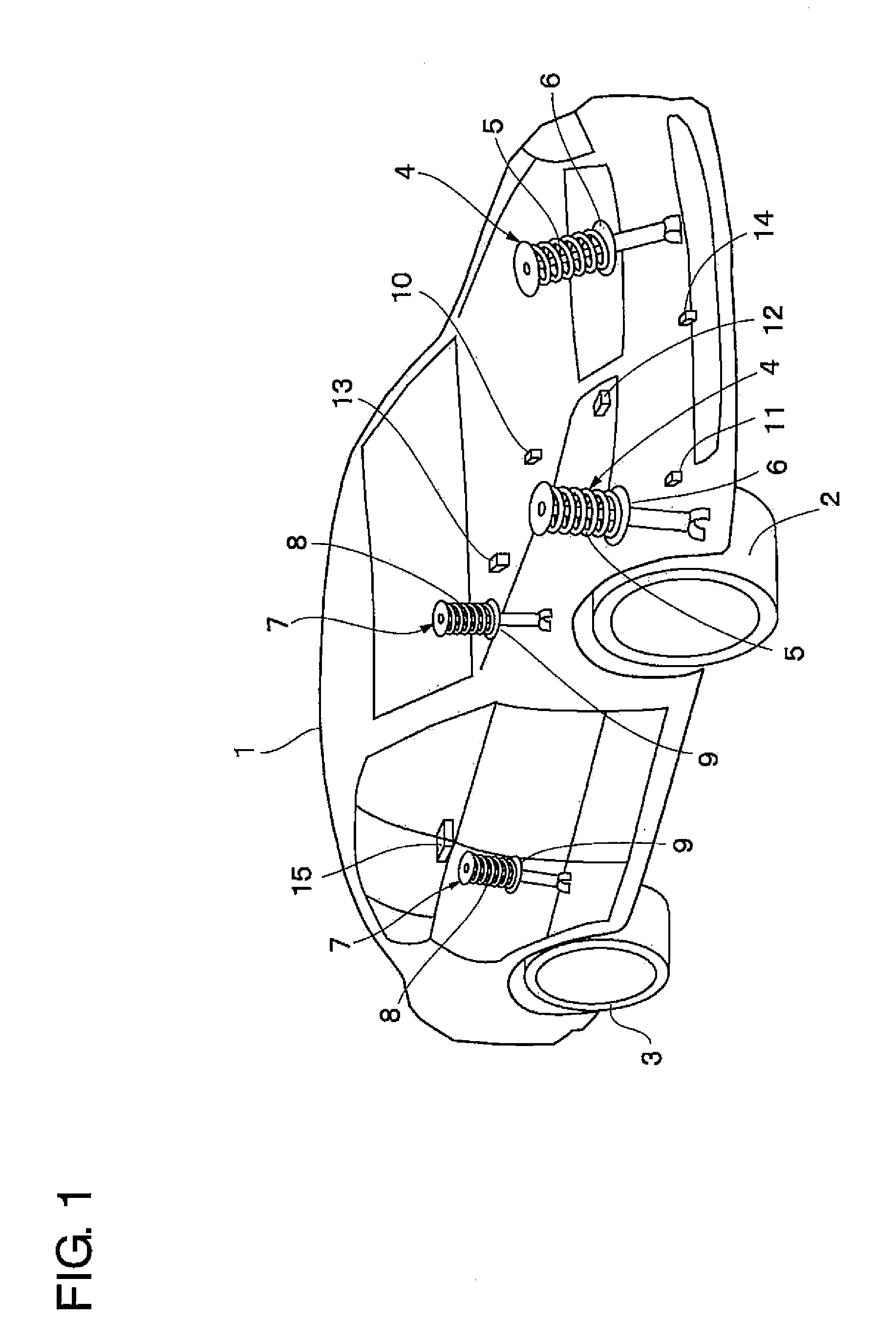
[0022]FIGS. 1 to 3 illustrate the present invention. FIG. 1 illustrates a vehicle body 1 constituting a body of a vehicle. Below the vehicle body 1, for example, front right and left wheels 2 (only one thereof is illustrated) and rear right and left wheels 3 (only one thereof is illustrated) are provided.
[0023]Front-wheel side suspension devices 4 are provided between the front right wheel 2 and the vehicle body 1 and between the front left wheel 2 and the vehicle body 1, respectively. One of the front-wheel side suspension devices 4 includes a right suspension spring 5 (hereinafter, referred to simply as “spring 5”) and a right damping-force adjusting type shock absorber 6 (hereinafter, referred to as “damping-force variable damper 6”) provided between the front right wheel 2 and the vehicle body 1 in parallel to the right spring 5. Similarly, the other front-wheel side suspension device 4 includes a left spring 5 and a left damping-force variable damper 6 provided between the fron...
second embodiment
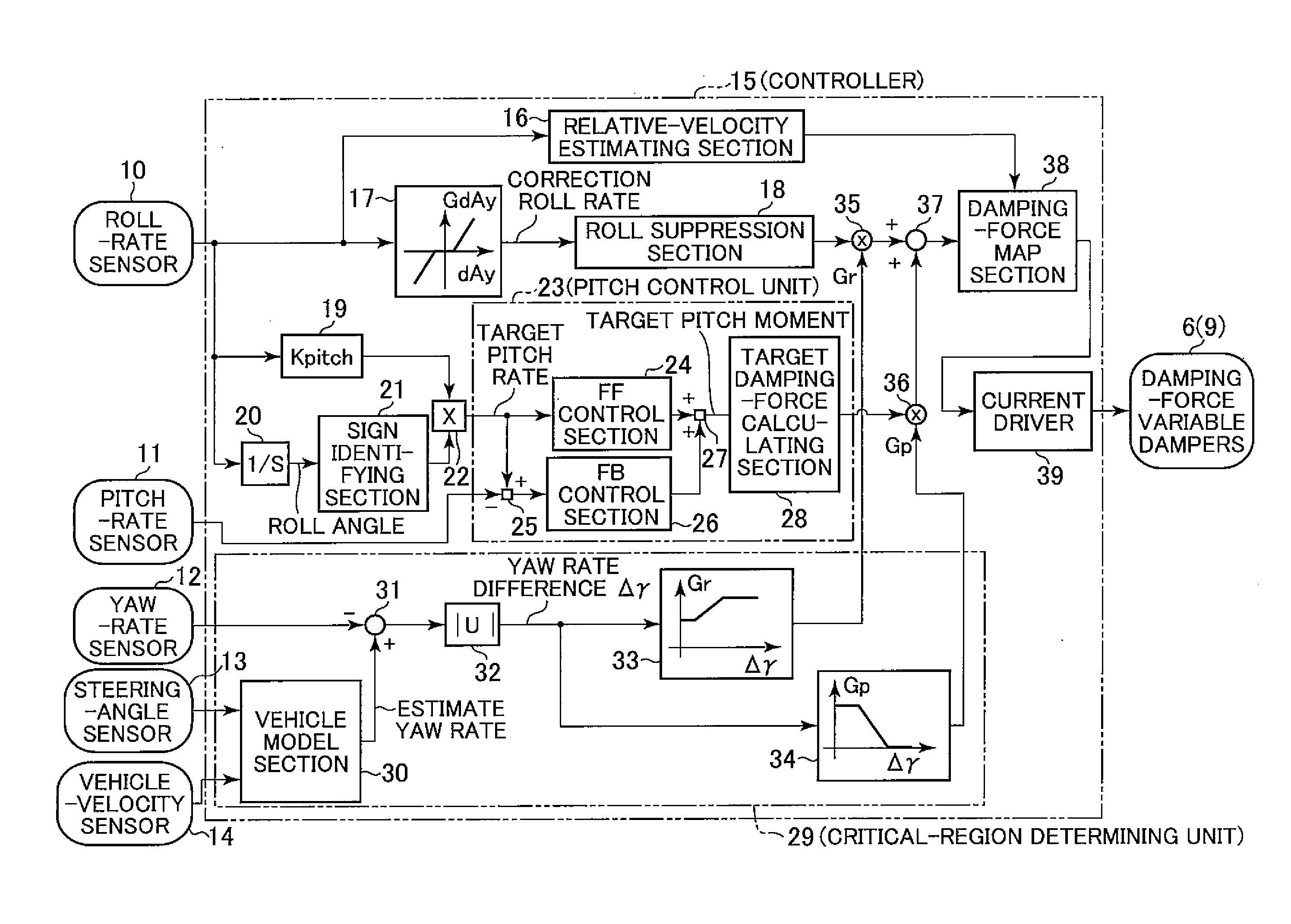
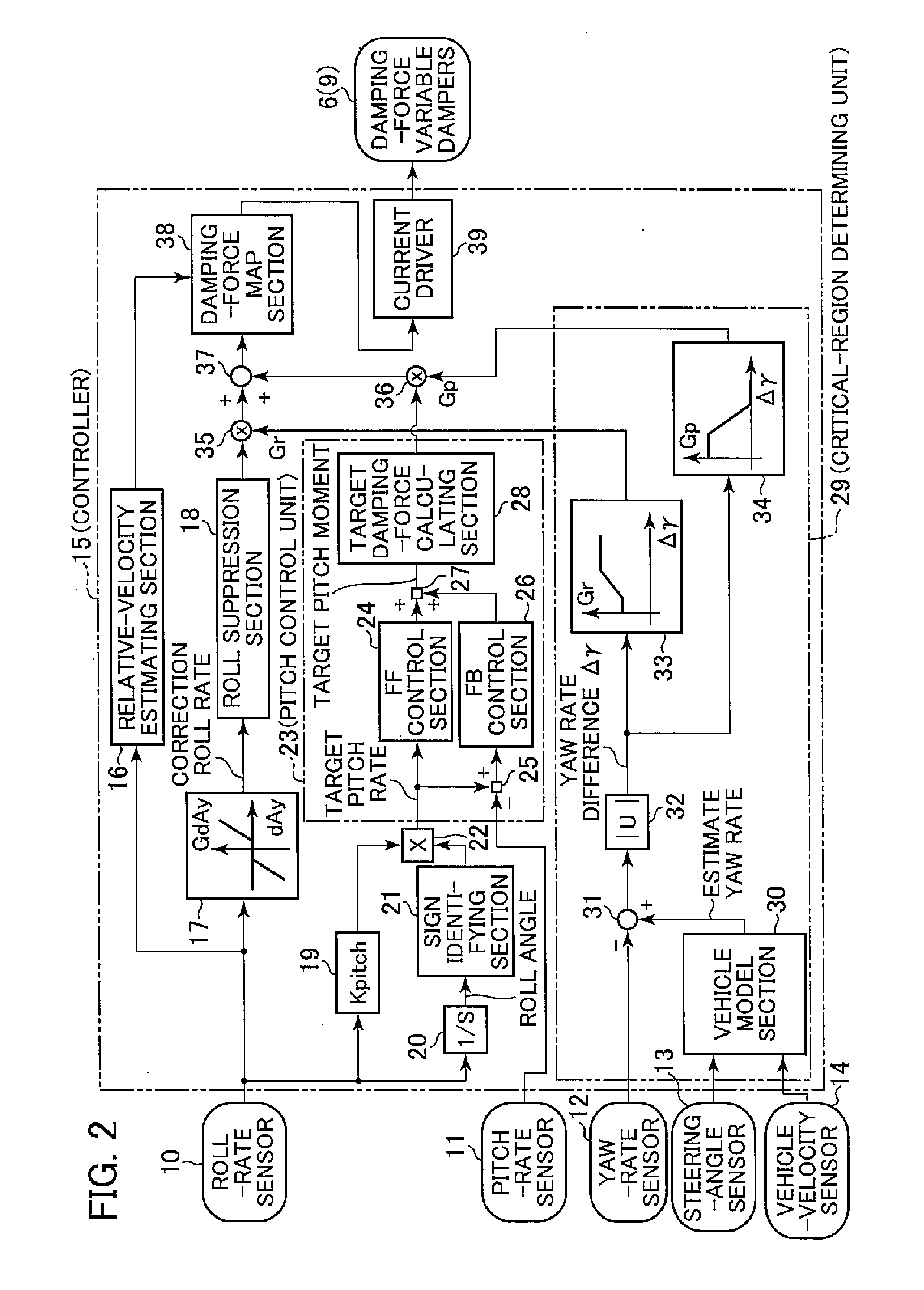
[0062]As illustrated in FIG. 2, a controller 41 is provided as control means used in the An input side of the controller 41 is connected to the yaw-rate sensor 12, the steering-angle sensor 13, and the vehicle-velocity sensor 14, whereas an output side thereof is connected to the actuators (not shown) of the damping-force variable dampers 6 provided on the front right wheel 2 side and the front left wheel 2 side and the damping-force variable dampers 9 provided on the rear right wheel 3 side and the rear left wheel 3 side.
[0063]As illustrated in FIG. 4, the controller 41 includes a vehicle model section 42, a roll gain multiplying section 43, a first filter section 44, a first differentiating section 45, an absolute-value computing section 46, a second differentiating section 47, a pitch gain multiplying section 48, a pitch control unit 49, and a second filter section 50. Moreover, similarly to the controller 15 described in the first embodiment, the controller 41 includes the rela...
third embodiment
[0088]In the third embodiment, in particular, the target thrusts FR, FL, RR, and RL for the respective wheels are calculated in the electromagnetic-damper control-amount calculating section 78 so that the electromagnetic dampers 79 (active suspensions) generate the thrusts in accordance with the target values. As a result, the pitch rate proportional to the roll rate can be generated. Therefore, a rotation axis of the vehicle body 1 can be stabilized to improve the roll feeling. In addition, the stability can also be improved.
[0089]In the third embodiment, the case where the target roll moment is equally distributed to the respective wheels in the block 78A of the electromagnetic-damper control-amount calculating section 78 illustrated in FIG. 6 and the target pitch moment is equally distributed to the respective wheels in the block 78C of the electromagnetic-damper control-amount calculating section 78 illustrated in FIG. 6 has been described as an example. However, the present inv...
PUM
Abstract
A vehicle attitude controller capable of improving turning operability, steering stability, and ride quality of a vehicle. In a normal-operation region, a pitchcontrol unit for calculating a target pitch rate in accordance with a roll rate performs control in priority to a roll suppression section. In this case, a target damping force calculated in the pitchcontrol unit is weighed to control a damping-force characteristic of the dampers so that a pitch rate becomes equal to the target pitch rate. In a critical region in which a road-surface gripping state of the vehicle tires is bad, the roll suppression section performs control in priority to the pitch control unit so as to weigh a target damping force calculated in the roll suppression section. As a result, the damping-force characteristic of the dampers is controlled so as to increase the amount of roll suppression control.
Description
BACKGROUND OF THE INVENTION[0001]The present invention relates to a vehicle attitude controller suitably used for a vehicle, for example, a four-wheeled automobile.[0002]In general, the following vehicle attitude controllers are known. One of the vehicle attitude controllers calculates a lateral acceleration from a steering angle and a vehicle velocity of a vehicle and then differentiates the lateral acceleration to obtain a lateral jerk. A damping force of each suspension for each of front and rear right / left wheels is switched in accordance with the lateral jerk to reduce a roll rate (for example, see Japanese Patent Application Laid-open No. 2007-290650).[0003]Another vehicle attitude controller obtains a target roll angle from a lateral acceleration obtained when a vehicle is running. After calculating a target pitch angle in accordance with the target roll angle, the vehicle attitude controller obtains a difference between the target pitch angle and an actual pitch angle so as ...
Claims
Application Information
Patent Timeline
Application Date:The date an application was filed.
Publication Date:The date a patent or application was officially published.
First Publication Date:The earliest publication date of a patent with the same application number.
Issue Date:Publication date of the patent grant document.
PCT Entry Date:The Entry date of PCT National Phase.
Estimated Expiry Date:The statutory expiry date of a patent right according to the Patent Law, and it is the longest term of protection that the patent right can achieve without the termination of the patent right due to other reasons(Term extension factor has been taken into account ).
Invalid Date:Actual expiry date is based on effective date or publication date of legal transaction data of invalid patent.

