Laser illumination system with reduced speckle

a laser source and annealing device technology, applied in the direction of polarising elements, instruments, manufacturing tools, etc., can solve the problems of reducing the image quality of components illuminated with laser sources, affecting the image quality of laser sources, and prone to speckle of laser sources,

Inactive Publication Date: 2012-04-05
PANASONIC CORP
View PDF5 Cites 53 Cited by
  • Summary
  • Abstract
  • Description
  • Claims
  • Application Information

AI Technical Summary

Benefits of technology

[0020]According to another aspect, there is provided a method to despeckle a laser beam, comprising generating a pulsed laser beam having a coherence length; transmitting the pulsed laser beam through a first transparent element comprising a plurality of microlenses so that the pulsed laser beam is output as a beamlet from each of the microlenses; and transmitting each one of the beamlets through a respective step included in a second transparent element comprising a plurality of the steps having a one-to-one correspondence with the plurality of microlenses, to an image plane, wherein a height of each step of at least two of the steps is configured to produce an optical path difference of the beamlets longer than the coherence length, wherein the second transparent element is disposed approximately at the foci of the beamlets output from the first transparent element. The generating of the pulsed laser beam may comprise driving the pulsed laser beam using a pulse of less than 10 nanoseconds. The method may further comprise collimating the generated pulsed laser beam and outputting the collimated generated pulsed laser beam to the first transparent element; and focusing the received beamlets transmitted through the respective steps by the second transparent element on the image plane using a field lens. The at least two of the steps may be configured as a one-dimensional staircase and the microlenses may be configured as a one-dimensional array of microlenses. The method may further comprise polarizing the pulsed laser beam with a linear polarization having a polarization direction; and changing the polarization direction of the pulsed laser beam by passing the pulsed laser beam through an optical wave plate comprising one of the steps of the second transparent element. The method may further comprise polarizing the pulsed laser beam with a linear polarization; and changing the linear polarization of the pulsed laser beam to right and left circular polarization by passing the pulsed laser beam through corresponding first and second optical wave plates each comprising one of the steps of the second transparent element. The method may further comprise transmitting each one of the beamlets output from the second transparent element through a third transparent element comprising another plurality of microlenses, to provide focus control of the beamlets.
[0021]According to another aspect, there is provided a two-dimensional despeckling unit, comprising a first transparent element comprising a surface having a plurality of microlenses to receive collimated light having a coherence length from a pulsed laser beam, each of the microlenses configured to output a beamlet which is shaped in two-dimensions; and a second transparent element comprising a light incident surface forming a two-dimensional area comprising two first boundaries and two second boundaries perpendicular to and connecting the two first boundaries; and a plurality of steps protruding out from the light incident surface and arranged in rows, wherein the steps in each row are configured to increase in height along a first direction parallel to the first boundaries, and the rows increase in height along a second direction parallel to the second boundaries, each of the steps having a different height from each other, and each of the steps being configured to receive a corresponding one of the beamlets; wherein the height of each step is configured to produce an optical path difference longer than the coherence length, and the light incident surface is disposed approximately at a foci of the beamlets output from the first transparent element.

Problems solved by technology

Because lasers emit coherent light, lasers may be prone to speckle.
Speckle patterns may severely degrade the image quality of components illuminated with a laser source, such as laser annealing, laser projection displays and laser microscopes.
However, devices that use dynamic reduction methods tend to be larger than those devices that use static reduction methods, for example, because of the number of additional mechanical components involved to generate the time-varying component.
Devices that use static reduction methods may also be large.
Microlens arrays, however, tend to give rise to speckle because in forming the ultimate image they merge the split beamlets.
First, because the incident beam 3 passes through the staircase element 1 and gets diffracted before entering the first fly's eye lens, the diffracted beamlets 4 may deviate in uniformity before entering the first fly's eye lens, thereby reducing the effectiveness of the despeckling.
Second, each of the beamlets 4 diffracted by the staircase element 1 can enter not only the respective targeted lenslet, but also an adjacent lenslet, thereby further reducing the effectiveness of homogenization by using the fly's eye system.

Method used


Image

  • Laser illumination system with reduced speckle
  • Laser illumination system with reduced speckle
  • Laser illumination system with reduced speckle

Examples


first embodiment

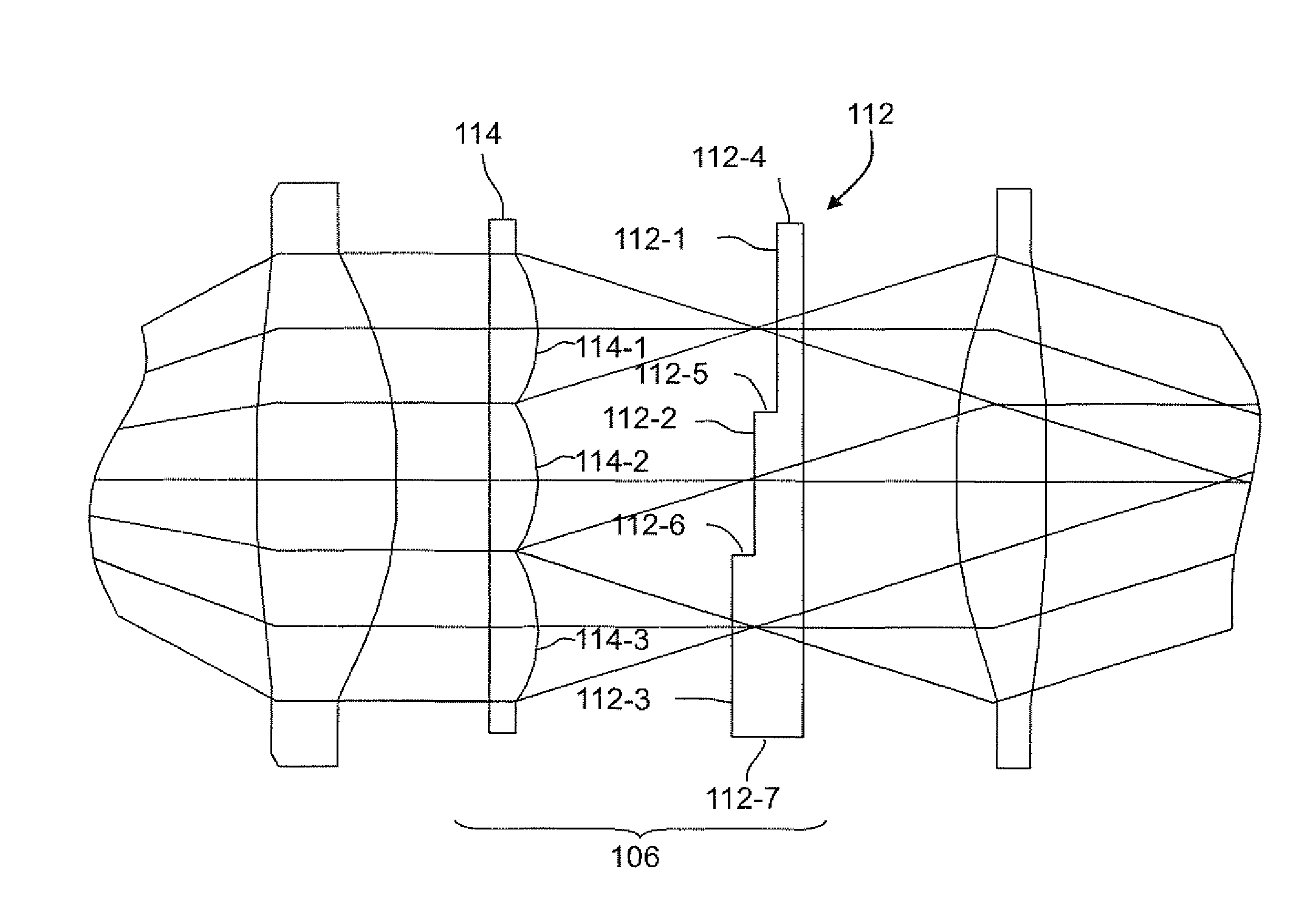
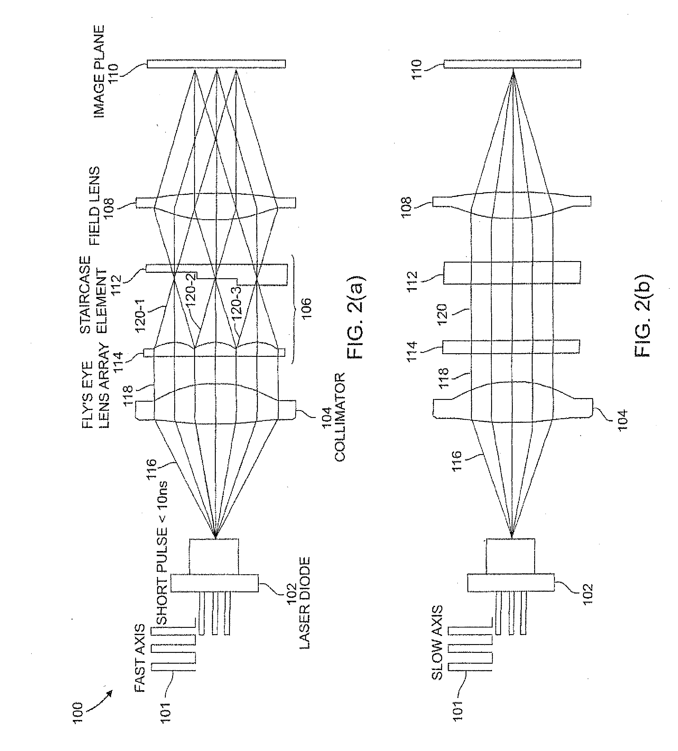
[0044]FIGS. 2(a) and 2(b) depict cross-sectional diagrams of an exemplary laser beam homogenizer 100 (also referred to herein as homogenizer 100), according to the present invention. In particular, FIG. 2(a) is a cross-section diagram of homogenizer 100 with respect to a fast axis of laser source 102; and FIG. 2(b) is a cross-section diagram of homogenizer 100 with respect to a slow axis of laser source 102. FIG. 3 is a magnified view of the despeckle elements or despeckle unit 106 shown in FIGS. 2(a) and 2(b).

[0045]Homogenizer 100 includes short pulse laser driver 101, laser source 102, collimator 104, despeckle elements 106 and field lens 108. In operation, laser source 102 emits coherent light beam 116. Collimator 104 collimates coherent light beam 116 received from laser source 102, to form collimated light beam 118. It is understood that collimator 104 may collimate coherent light beam 116 to form collimated light (collimated light with no divergence) or approximately collimate...

third embodiment

[0092]Since linearly polarized (e.g., p-polarized) and orthogonally polarized (e.g., s-polarized) beams do not interfere with each other, no step needs to be added to one of the two adjacent positions on the staircase configuration. Accordingly, wave plates 602-1, 602-2 and 602-3 may be formed directly on the physical steps 612-1, 612-2, and 612-3 without increasing the step height. Accordingly, a thickness of the despeckle element 600 may be reduced to half of the thickness and half the number of physical steps of a despeckle element where the optical steps are formed only using physicals steps as optical path difference elements (e.g., three physical steps in FIG. 6 as opposed to six physical steps of a corresponding despeckle element similar to despeckle element 106 of FIG. 2(a) but having six steps). Thus, the despeckling element 600 according to the present invention has a reduced total thickness and is very compact.

[0093]Furthermore, although FIG. 6 illustrates the wave plates...

fourth embodiment

[0101]Since right circular polarization and left circular polarization beams do not interfere with each other, no step needs to be added to one of the two adjacent positions on the staircase configuration. Accordingly, both first wave plate 702 and second wave plate 704 may be formed directly on staircase element 712 without increasing the step height. Thus, the thickness of despeckle element 700 may be reduced to half of the thickness and half the number of physical steps (e.g., three physical steps as opposed to six physical steps) compared to a step of despeckle element 106 (FIG. 2(a)) but having six steps. Thus, the despeckling element 700 according to the present invention has a reduced total thickness and is very compact.

[0102]Furthermore, although FIG. 7 illustrates the wave plates 702 and 704 as being disposed on the steps 712-1, 712-2, and 712-3 of the staircase element 712, it should be understood that the wave plates 702 and 704 are not limited to being disposed on the st...


PUM

PropertyMeasurementUnit
output poweraaaaaaaaaa
transparentaaaaaaaaaa
coherence lengthaaaaaaaaaa

Abstract

A despeckling device and method in which an optical path difference staircase element is disposed between a fly's eye lens array and the image plane in a position near the focus position of the fly's eye lens array, and a laser generating unit generates and transmits pulsed laser beams to the optical path difference staircase element, wherein the pulsed laser beams are driven at a very short pulsed rate.

Description

CROSS-REFERENCE TO RELATED APPLICATIONS[0001]This application is related to and claims the benefit of provisional U.S. application No. 61 / 388,238 filed Sep. 30, 2010.FIELD OF THE INVENTION[0002]This invention relates to a laser annealing device with reduced speckle, especially to a laser annealing machine to create a thin film transistor for a large size organic LED display. This invention also relates to laser display devices and laser display methods, and more particularly, to laser display devices and laser display methods directed to achieving reduced speckle.RELATED ART[0003]In general, a laser is an optical source that emits a coherent light beam (also referred to herein as “coherent light” or “laser light”). The coherent light may be emitted as a relatively narrow beam and may be focused to very small spots. Because lasers emit coherent light, lasers may be prone to speckle. Speckle is a random intensity pattern on reflection from a diffuse surface generally caused by mutual ...

Claims


Application Information

Patent Timeline
Patent Type & Authority Applications(United States)
IPC IPC(8): B23K26/00G02B27/28G02B27/48
CPCG02B27/48G02B27/286
Inventor MIZUYAMA, YOSUKELETO, RICCARDO
Owner PANASONIC CORP
Why Eureka
Try Eureka