
Control of an electrical machine

a technology of electrical machines and control circuits, applied in the direction of electronic commutators, single motor speed/torque control, synchronous motor starters, etc., can solve the problems of prolonged life of electrical machines, achieve simple and thus cheap circuits, improve the efficiency of electrical machines, and simplify the control of electrical machines.

Active Publication Date: 2012-04-05
DYSON TECH LTD
View PDF3 Cites 29 Cited by
  • Summary
  • Abstract
  • Description
  • Claims
  • Application Information

AI Technical Summary

Benefits of technology

The present invention provides a method of controlling an electrical machine that improves its efficiency by adjusting the overcurrent threshold based on changes in the supply voltage and speed of the machine. This allows for a reduction in harmonics within the phase winding waveform and a gradual increase in torque of the machine. The method may include sequentially exciting and freewheeling the phase winding over each electrical half-cycle, adjusting the threshold accordingly, and optimizing the power profile over a range of voltages and speeds. The method may also involve adjusting the freewheel period, the length of the conduction period, and the point at which the phase winding is commutated. The invention provides a simple and cost-effective way to control the electrical machine and improve its efficiency.

Problems solved by technology

This then reduces the stresses placed on mechanical components of the electrical machine and thus the lifespan of the electrical machine may be prolonged.

Method used


Image

  • Control of an electrical machine
  • Control of an electrical machine
  • Control of an electrical machine

Examples


Embodiment Construction

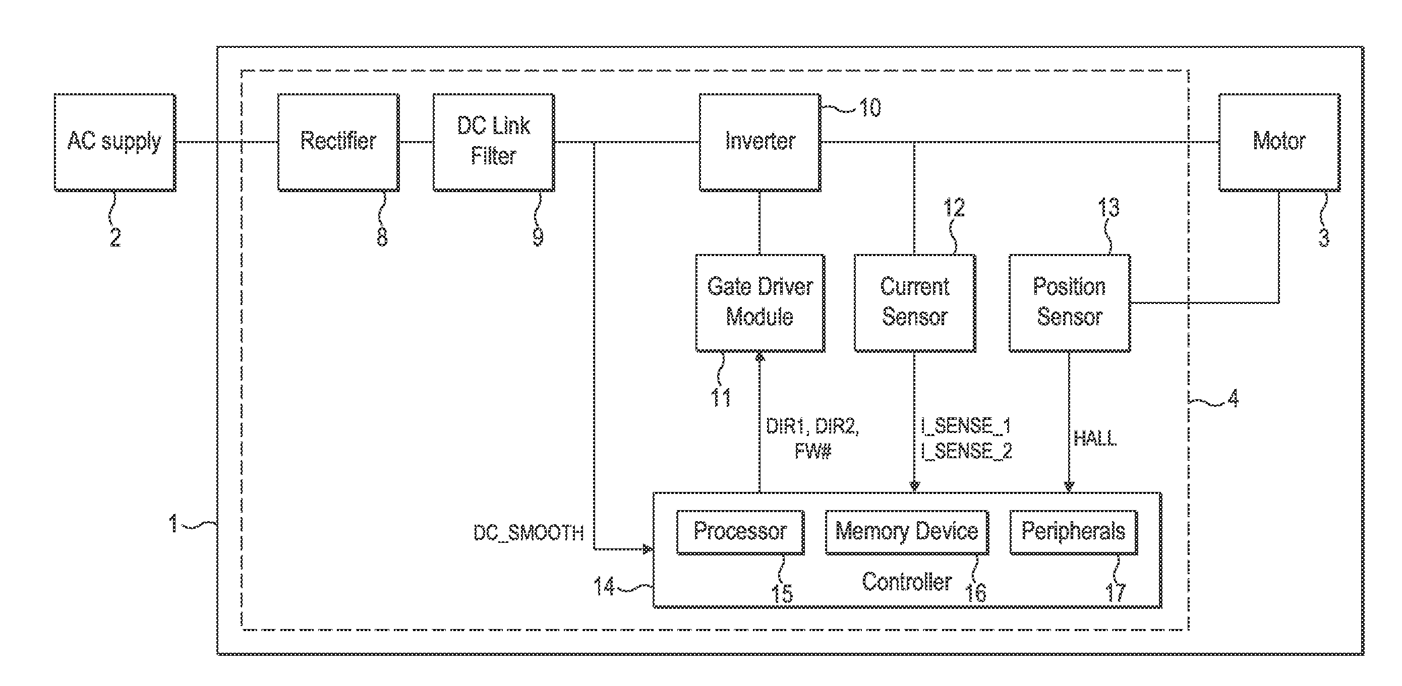
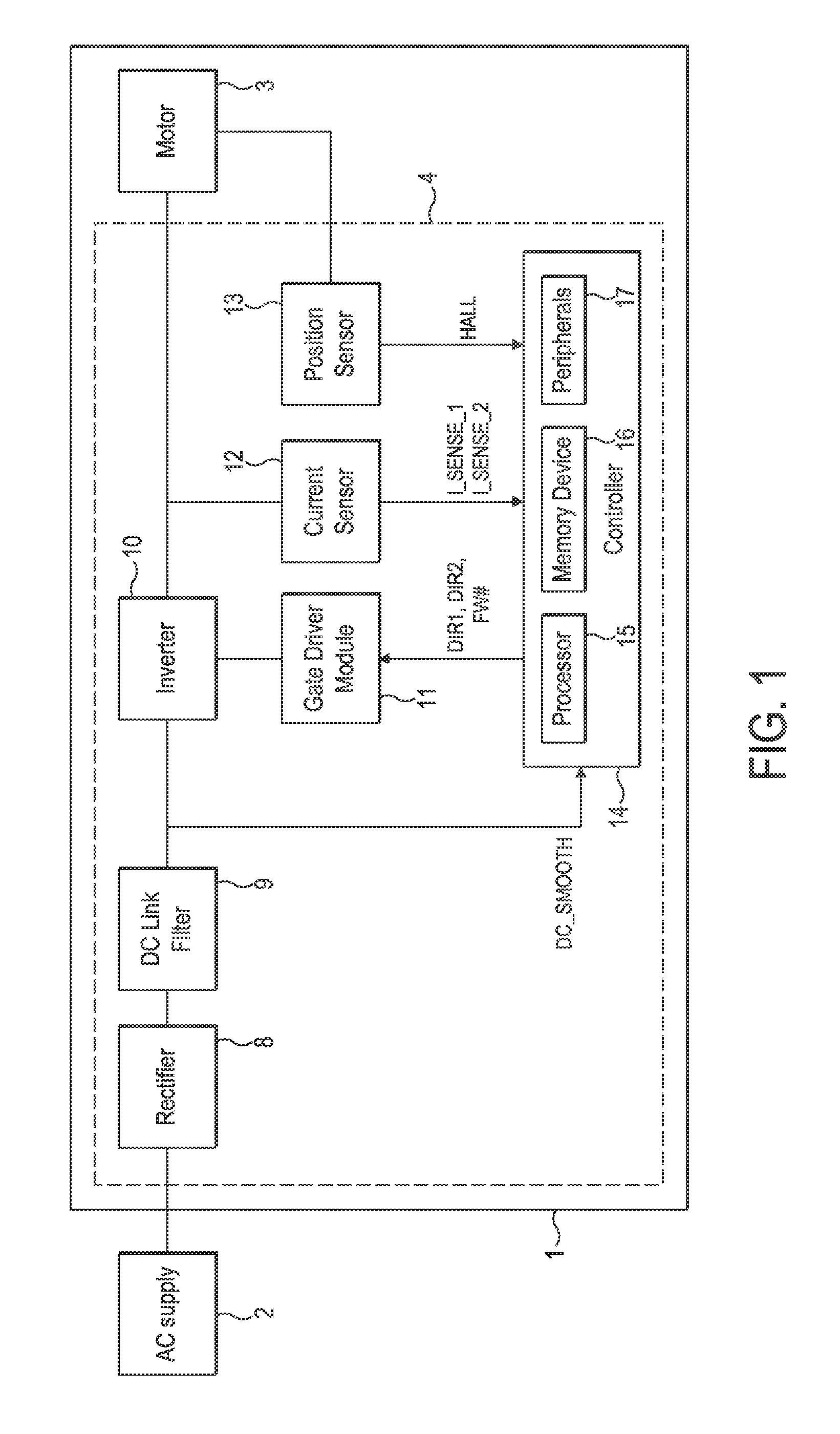
[0029]The motor system 1 of FIGS. 1 to 3 is powered by an AC power supply 2 and comprises a brushless motor 3 and a control system 4.

[0030]The motor 3 comprises a four-pole permanent-magnet rotor 5 that rotates relative to a stator 6. The stator 6 comprises a pair of c-shaped cores that define four stator poles. Conductive wires are wound about the cores and are coupled together to form a single phase winding 7.

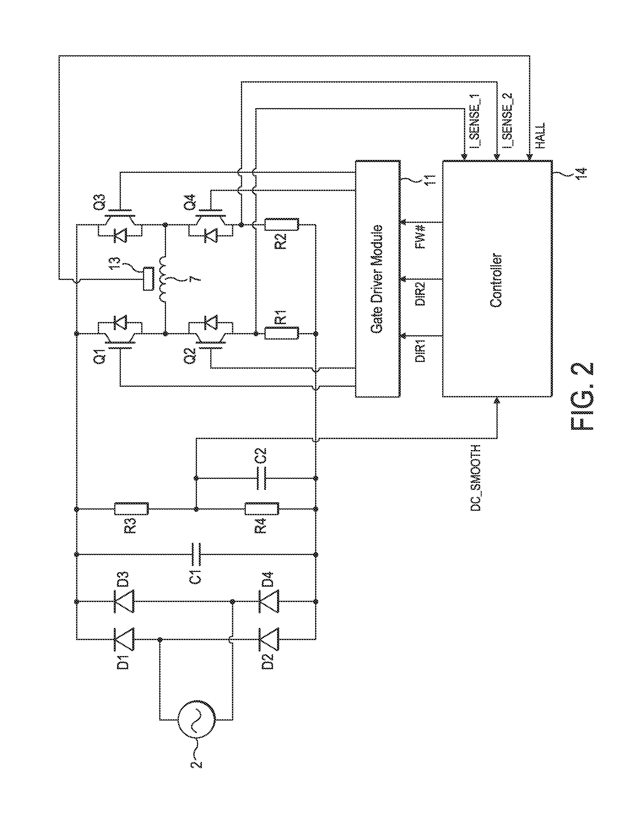
[0031]The control system 4 comprises a rectifier 8, a DC link filter 9, an inverter 10, a gate driver module 11, a current sensor 12, a rotor-position sensor 13, and a controller 14.

[0032]The rectifier 8 comprises a full-wave bridge of four diodes D1-D4 that rectify the output of the AC power supply 2 to provide a DC voltage.

[0033]The DC link filter 9 comprises a capacitor C1 that smoothes the relatively high-frequency ripple that arises from switching of the inverter 10. If required, the DC link filter 9 may additionally smooth the rectified DC voltage at the fundamental fre...


PUM


Abstract

A method of controlling an electrical machine that includes exciting a phase winding with a supply voltage, and freewheeling the phase winding when current in the phase winding exceeds a threshold. The threshold is then adjusted in response to changes in the supply voltage and / or the speed of the electrical machine. Additionally, a control system that implements the method and an electrical machine comprising the control system are described.

Description

REFERENCE TO RELATED APPLICATIONS[0001]This application claims the priority of United Kingdom Application No. 1016687.4, filed Oct. 4, 2010, the entire contents of which are incorporated herein by reference.FIELD OF THE INVENTION[0002]The present invention relates to control of an electrical machine.BACKGROUND OF THE INVENTION[0003]An electrical machine is typically driven by a control system that controls the excitation of phase windings. The control system may adjust the turn-on and turn-off angles of excitation in response to changes in the speed of the electrical machine so as to maximize output power or minimize torque ripple. However, little attention is generally given to the efficiency of the electrical machine.SUMMARY OF THE INVENTION[0004]In a first aspect, the present invention provides a method of controlling an electrical machine, the method comprising exciting a phase winding of the electrical machine with a supply voltage, sensing current in the phase winding, freewhe...

Claims


Application Information

Patent Timeline
Patent Type & Authority Applications(United States)
IPC IPC(8): H02P6/08
CPCH02P6/008H02P23/0081H02P6/142H02P6/26H02P6/15H02P23/26H02P6/28H02P29/032H02P6/06
Inventor LEAVER, MARK EDWARDCHEN, YUCELIK, TUNCAY
Owner DYSON TECH LTD
Learn More