
Probe card

a technology of probe card and ceramic board, which is applied in the direction of measurement device, semiconductor/solid-state device testing/measurement, instruments, etc., can solve the problems of increased fabrication cost, complicated fabrication process, and difficult fabrication of ceramic board for space transformer corresponding to 300 mm wafers, and achieve excellent productivity and excellent signal integrity

Inactive Publication Date: 2012-04-05
AMST CO LTD
View PDF3 Cites 7 Cited by
  • Summary
  • Abstract
  • Description
  • Claims
  • Application Information

AI Technical Summary

Benefits of technology

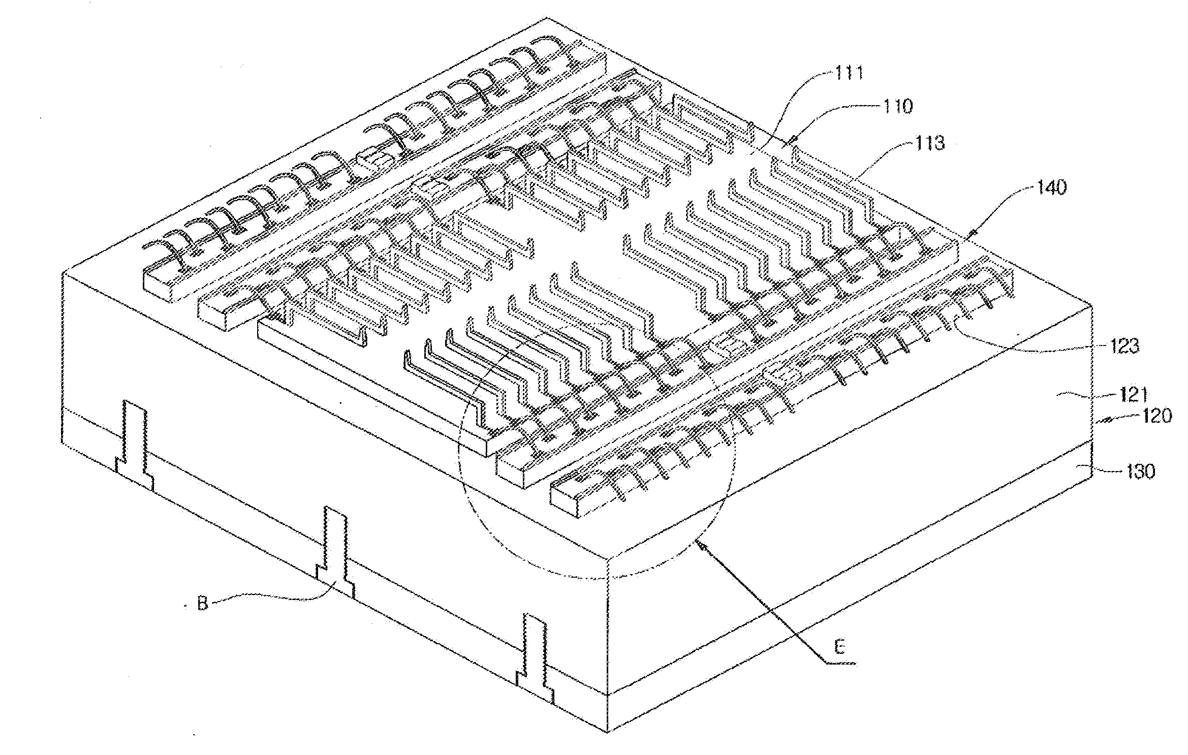
[0027]In the disclosed probe card, the lower surface circuit board mounted to the space transformer has a large area corresponding to an area of the space transformer body, so that there is an advantage in that the main circuit board can be used for general purpose irrespective of the pattern of the probe module in a state where the lower surface circuit board is connected to the main circuit board.
[0028]In the disclosed probe card, the standing conductive medium is mounted to the space transformer body in the state where the standing conductive medium is mounted on the lower surface circuit board, so that a problem in which a vertical conductive medium and a lower circuit board are arranged to correspond to each probe module as in the related art can be solved.
[0029]In the disclosed probe card, the standing conductive medium is mounted on the lower surface circuit board, and the standing conductive medium is inserted into the penetration portion of the space transformer to be mounted. Therefore, the mounting operation is effective in terms of operation as compared with an operation of inserting the vertical conductive medium into the penetration portion provided in the space transformer body and bonding both ends of wires to the vertical conductive medium and the lower circuit board as in the related art, so that there are advantages in that productivity is excellent and the probe card is structurally stable.
[0030]In the disclosed probe card, the electrical signal applied to the main circuit board is branched off from the lower surface circuit board via the mutual connection member. Thus, the distance from the branched point to the probe module is shorter than the distance branched off from the existing main circuit board. Therefore, there is an advantage in that signal integrity is excellent.

Problems solved by technology

However, unlike a general ceramic board, the ceramic board for the space transformer is equipped with electric wiring for electrical connection between the probe and a circuit board, and, hence, there are problems in that the fabrication process thereof is complicated, which results in increased fabrication cost.
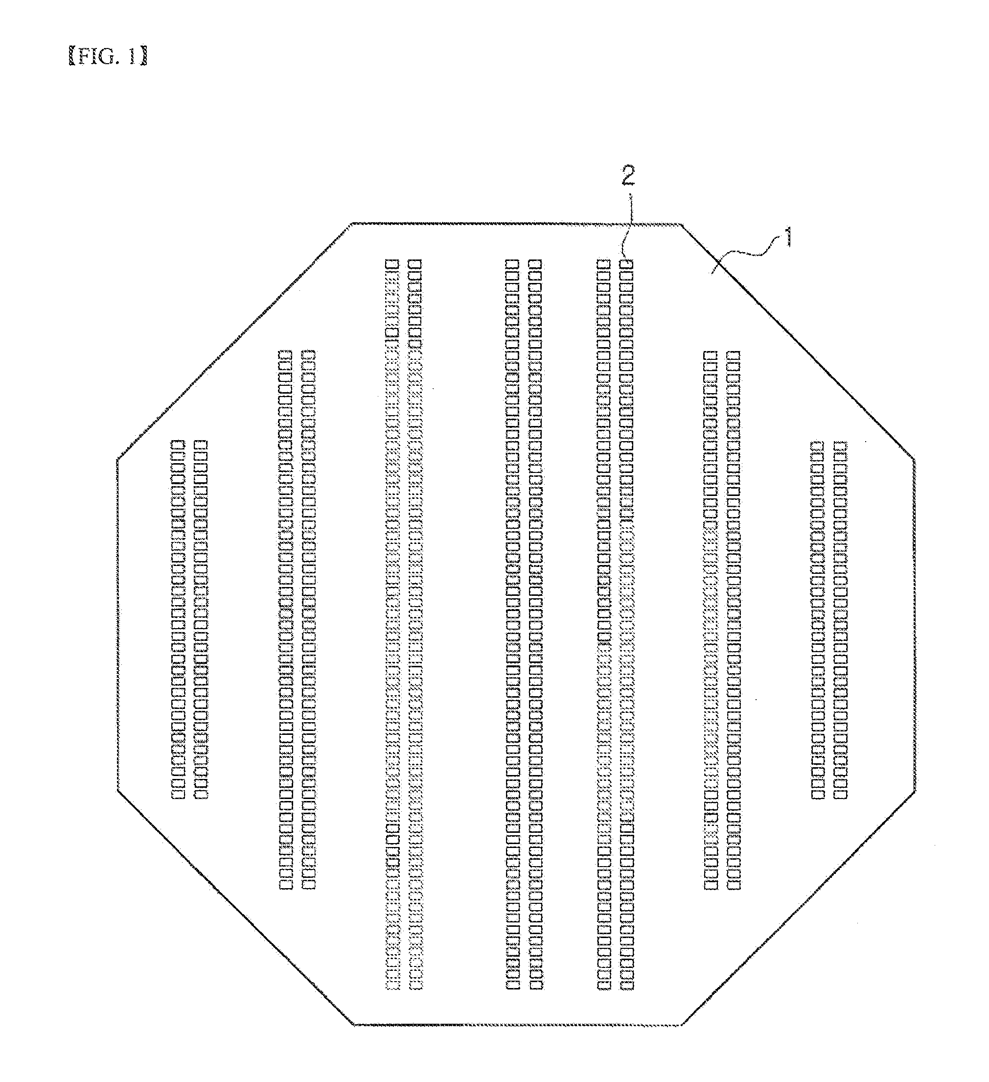
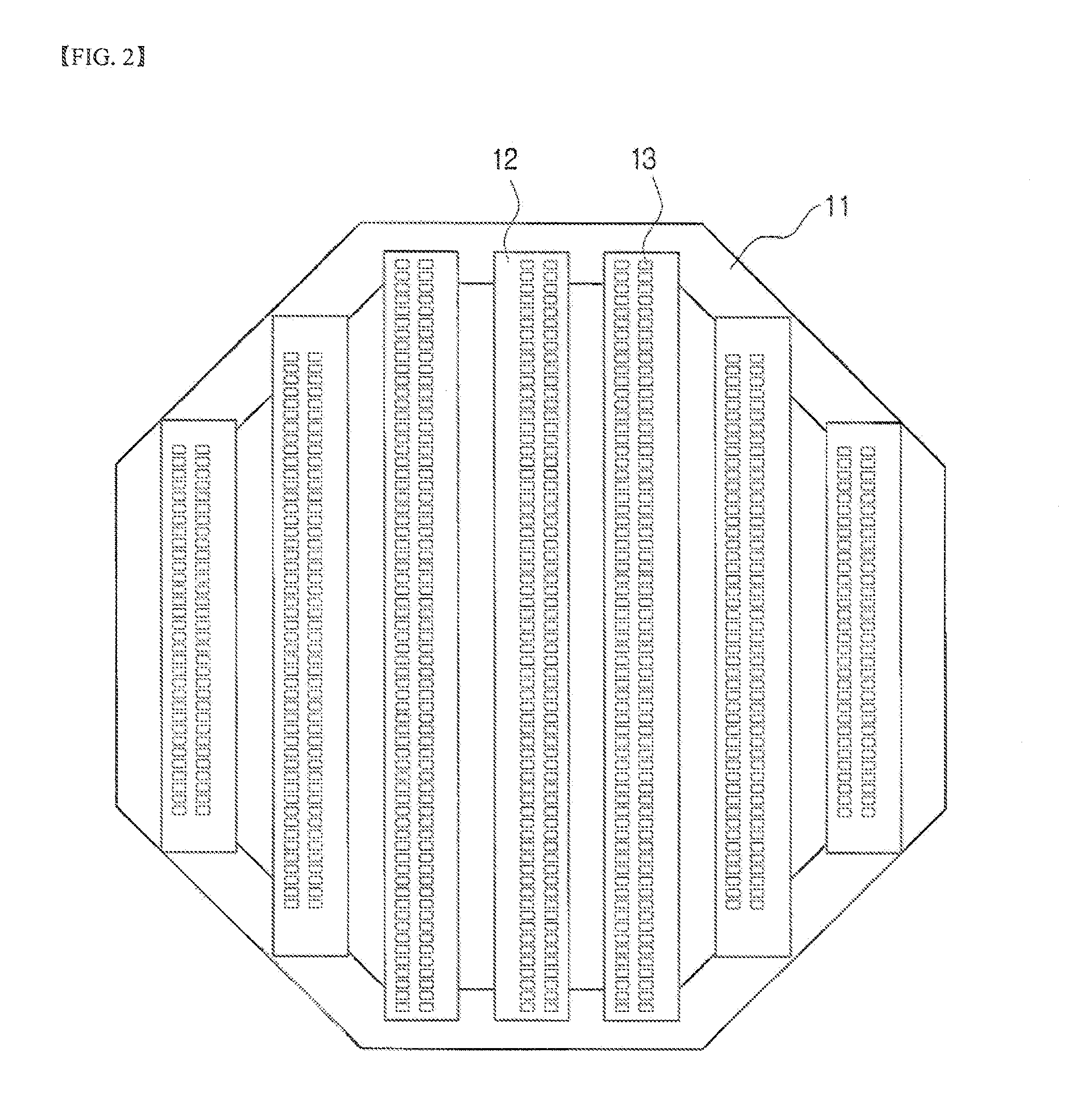
The problem of the ceramic board for the space transformer described above becomes more serious for a large-area board, and currently, fabrication of a ceramic board for a space transformer corresponding to a 300 mm wafer is difficult.
However, as the area to be tested is increased, the number of blocks and the lengths of the blocks to be precisely arranged also increase, so that there are problems in that time consumed to precisely arrange the blocks is increased and an arrangement of the blocks may be deteriorated when the probe card is exposed to a test environment to be used.
Therefore, it is difficult to use the main circuit board for general purposes.
Furthermore, since a body 21, the lower circuit board 40, and the main printed circuit board of the space transformer 20 are set depending on the pattern of the unit probe module 30, there is a disadvantage in that when the pattern of the unit probe module 30 is changed, a pattern of the lower circuit board 40 and the main printed circuit board have to be changed.
Therefore, there is a disadvantage in that the distance from the main circuit board 60 to the unit probe module 30 is far and thus signal integrity is unstable.
Moreover, a channel between the main circuit board 60 and the unit probe module 30 is limited by the lower circuit board 40 of which the position is limited, so that there is a difficulty in controlling the space transformer 20.

Method used


Image

  • Probe card
  • Probe card
  • Probe card

Examples


Embodiment Construction

[0049]Exemplary embodiments now will be described more fully hereinafter with reference to the accompanying drawings, in which exemplary embodiments are shown. This disclosure may, however, be embodied in many different forms and should not be construed as limited to the exemplary embodiments set forth therein. Rather, these exemplary embodiments are provided so that this disclosure will be thorough and complete, and will fully convey the scope of this disclosure to those skilled in the art. In the description, details of well-known features and techniques may be omitted to avoid unnecessarily obscuring the presented embodiments.

[0050]The terminology used herein is for the purpose of describing particular embodiments only and is not intended to be limiting of this disclosure. As used herein, the singular forms a, an and the are intended to include the plural forms as well, unless the context clearly indicates otherwise. Furthermore, the use of the terms a, an, etc. does not denote a...


PUM


Abstract

Provided is a probe card which has a space transformer which may be effectively changed to correspond to a change in wafer chip structure and is capable of maximizing acceptable channels of the space transformer. The probe card for testing a semiconductor chip on a wafer includes: a space transformer body in which a plurality of unit probe modules are arranged at intervals; a main circuit board to which an electrical signal is applied from an external test device; a reinforcement plate for supporting the main circuit board such that the unit probe modules become stable against an external effect; a standing conductive medium which is inserted into a penetration portion provided in the space transformer body; a lower surface circuit board in which the standing conductive medium is electrically connected to the unit probe module as a flexible conductive medium and the standing conductive media are mounted; and a mutual connection member for electrically connecting the lower surface circuit board to the main circuit board.

Description

TECHNICAL FIELD[0001]This disclosure relates to a probe card, and more particularly, to a probe card which has a space transformer which is effectively changed to correspond to a change in wafer chip structure and is capable of maximizing acceptable channels of the space transformer.BACKGROUND ART[0002]In general, a semiconductor fabrication process is divided into preprocessing and postprocessing. The preprocessing is a fabrication process for forming an integrated circuit pattern on a wafer, and the postprocessing is an assembling process for separating a wafer into a plurality of chips, connecting a conductive lead or ball to each chip for transmission of an electrical signal to an external device, and performing molding on the chip with epoxy or the like, thereby configuring an integrated circuit package.[0003]Before performing the assembling process, an electrical die sorting (EDS) process for inspecting electrical characteristics of each chip is performed. The EDS process is a...

Claims


Application Information

Patent Timeline
IPC IPC(8): G01R1/067
CPCG01R1/06727G01R31/2889G01R1/07342H01L22/00
Inventor SHIM, YUN HEEYOON, SUNG HEEYOO, SEUNG HOSONG, BYUNG CHANGCHUNG, IN BUHMKIM, DONG IL
Owner AMST CO LTD
Learn More