Inductive Device

a technology of inductive devices and inductive coils, which is applied in the direction of transformers/inductances magnetic cores, continuously variable inductances/transformers, and cores/yokes, etc., can solve the problems of winding and core loss problems, adverse effects on the power conditioning unit, and general inability to address the problem of winding and core loss, etc., to reduce the loss of direct current resistance and reduce the loss of ac proximity winding loss, the effect of d

Inactive Publication Date: 2012-04-05
SILVA ARTURO
View PDF0 Cites 8 Cited by
  • Summary
  • Abstract
  • Description
  • Claims
  • Application Information

AI Technical Summary

Benefits of technology

[0005]This arrangement can provide a choke inductor structure for use in current shaping applications such as might be required in power factor correction (PFC) circuits. It will be noted that the shape of each gap in the inductor controls a slope between two inductance values as a function of load current. In other words, the nature of the gaps determines the saturation points of the core. It has been found that this arrangement can therefore provide low total harmonic distortion (THD) AC output waveforms to achieve high efficiency.
[0015]The flat wire coil may be wound in a single layer on the core body to reduce AC proximity winding loss.

Problems solved by technology

The leaking magnetic flux causes an eddy current in the coil which heats the coil and can cause interference in other components of the power conditioning units.
The temperature rise arising from winding loss and core loss therefore has an adverse effect on the power conditioning units.
Conventional circuits, e.g. continuous conduction mode (CCM) power factor correction (PFC) circuits, are generally unable to address the problems associated with the winding and core losses.

Method used


Image

  • Inductive Device
  • Inductive Device
  • Inductive Device

Examples


Embodiment Construction

Power Conditioning Units

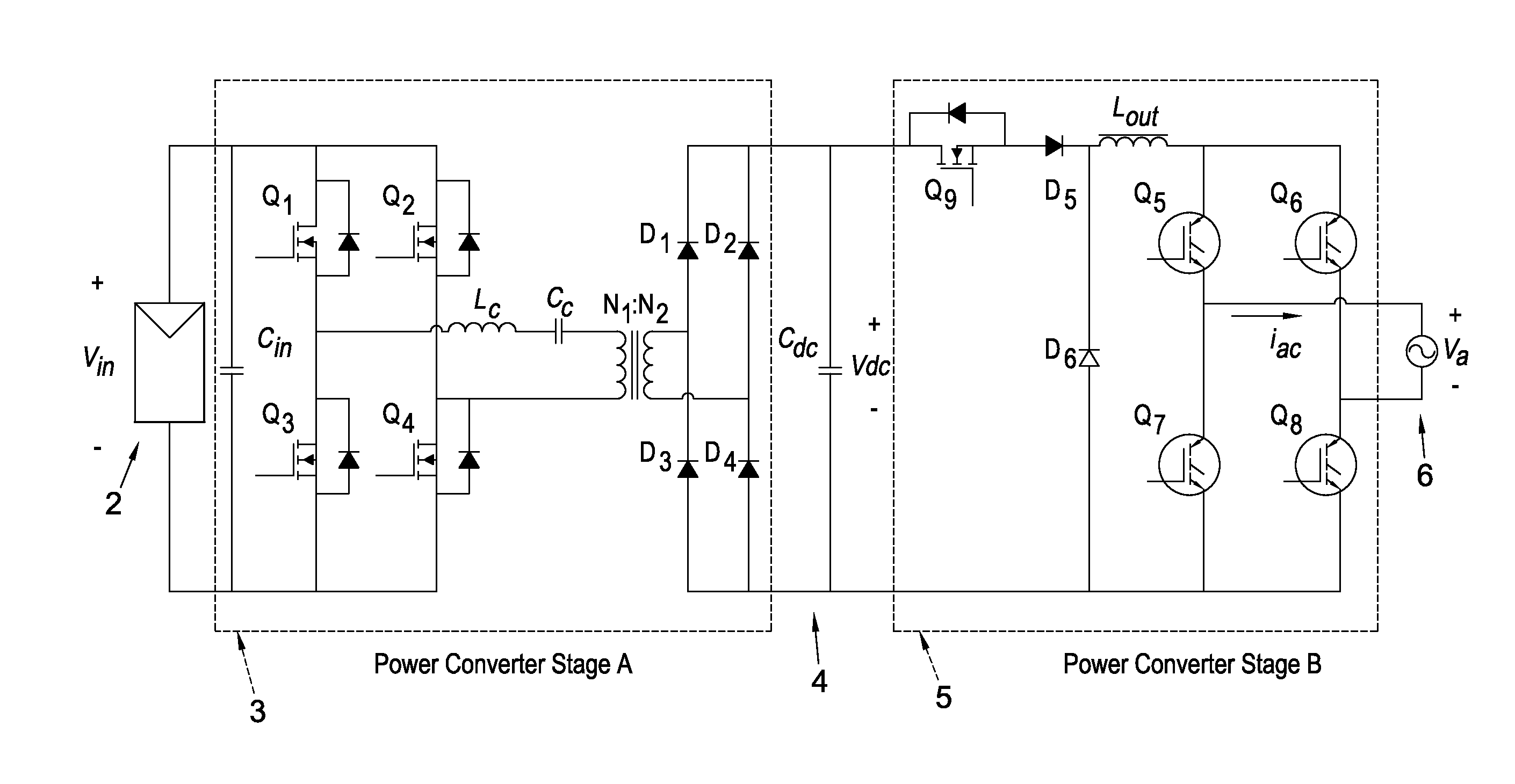
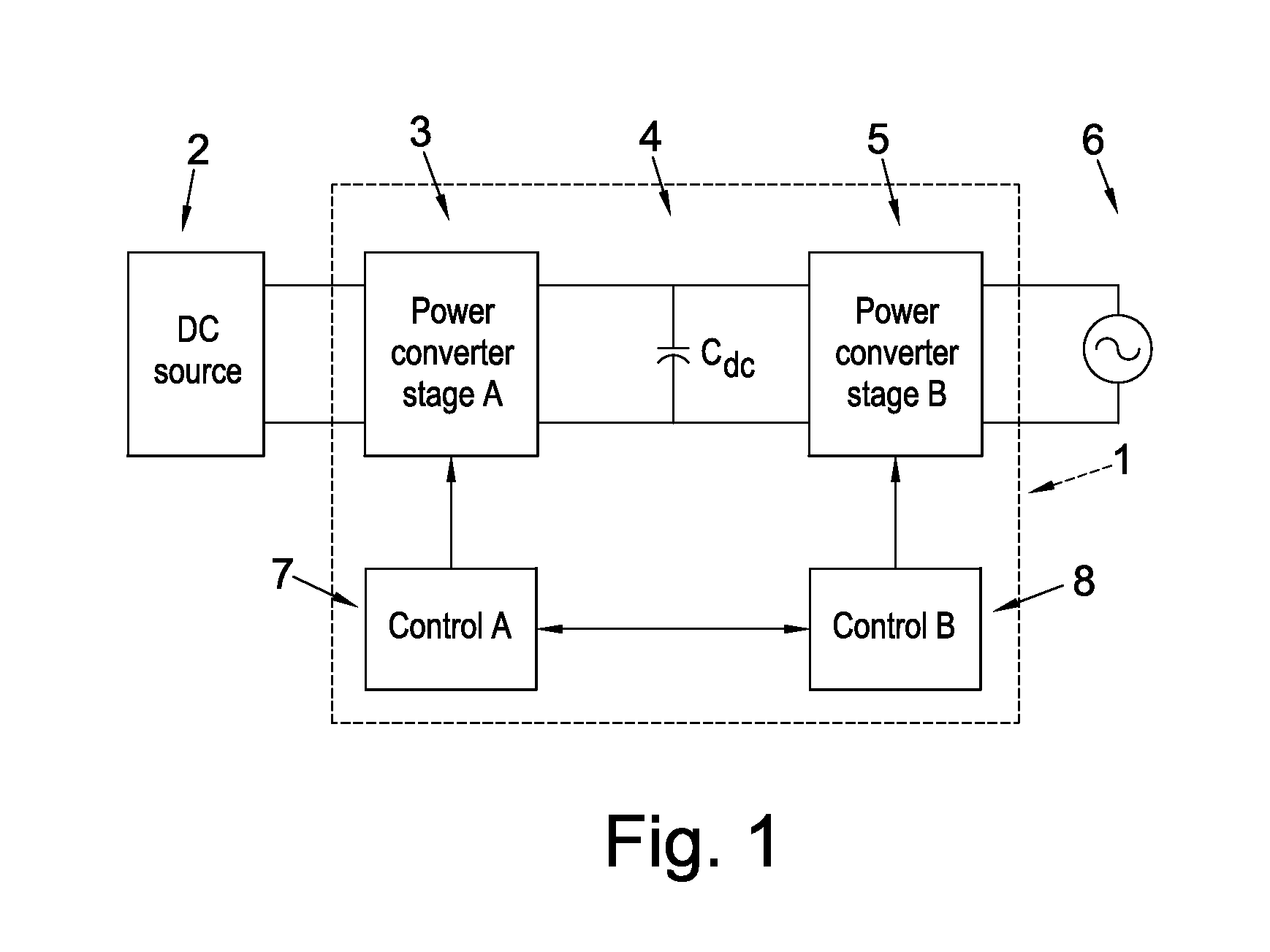
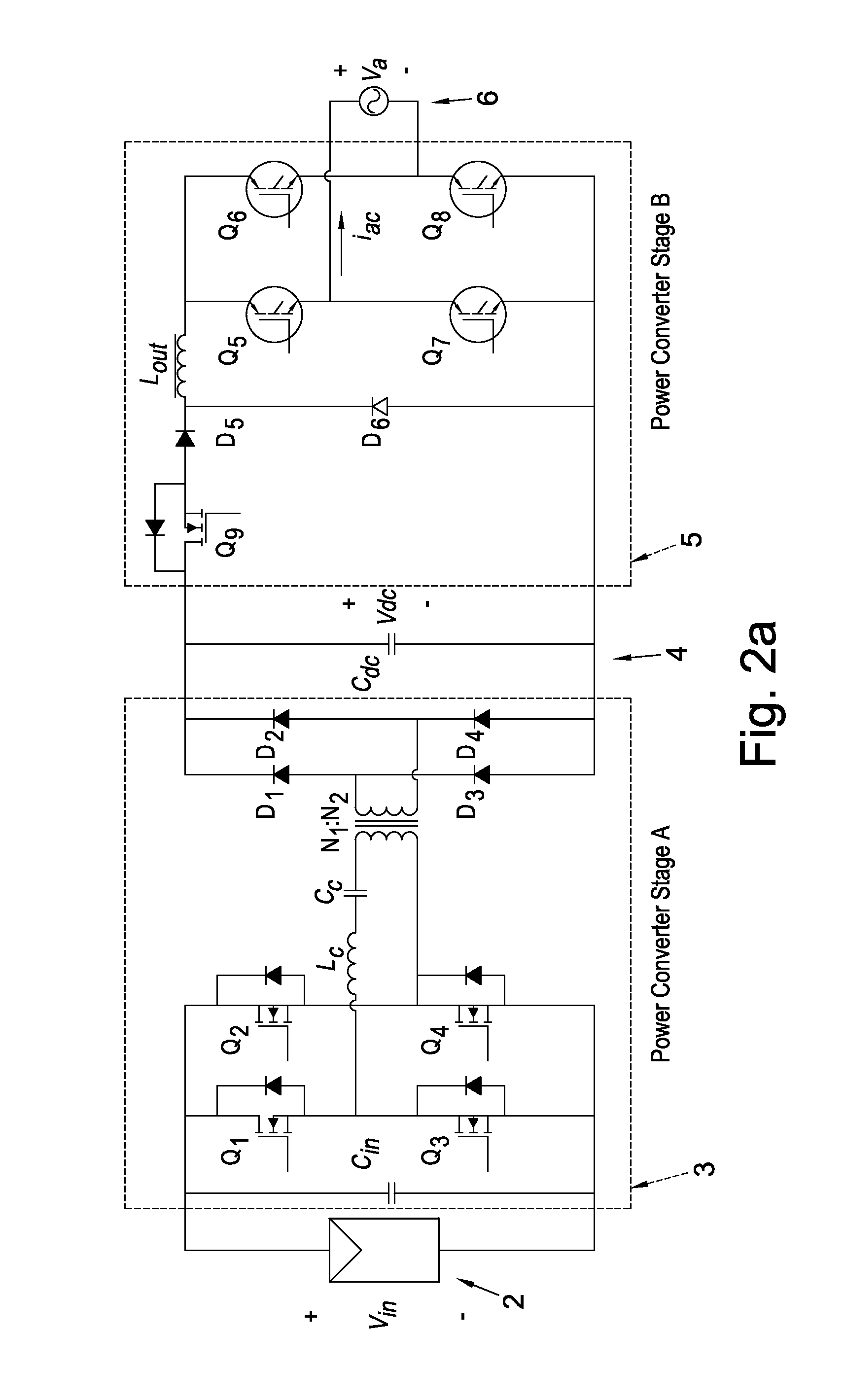
[0040]By way of background, we first describe an example photovoltaic power conditioning unit. Thus FIG. 1 shows photovoltaic power conditioning unit of the type we described in WO2007 / 080429. The power converter 1 is made of three major elements: a power converter stage A, 3, a reservoir (dc link) capacitor Cdc 4, and a power converter stage B, 5. The apparatus has an input connected to a direct current (dc) power source 2, such as a solar or photovoltaic panel array (which may comprise one or more dc sources connected in series and / or in parallel). The apparatus also has an output to the grid main electricity supply 6 so that the energy extracted from the dc source is transferred into the supply. Capacitor Cdc is preferably non-electrolytic, for example a film capacitor.

[0041]The power converter stage A may be, for example, a step-down converter, a step-up converter, or it may both amplify and attenuate the input voltage. In addition, it generally provides ...


PUM

PropertyMeasurementUnit
frequencyaaaaaaaaaa
frequencyaaaaaaaaaa
frequencyaaaaaaaaaa

Abstract

We describe an inductive device for use in current shaping applications. The inductive device includes a core body comprising a first gap and a second gap, and at least one transition region between the first and second gaps. The shape of each gap in the inductive device can control a slope between two inductance values as a function of load current. The inductive device is capable of providing low total harmonic distortion (THD) AC output waveforms to achieve high efficiency.

Description

FIELD OF THE INVENTION[0001]The present invention relates to an inductive device for use in current shaping applications. Particularly, but not exclusively, the invention relates to an inductive device for use in a photovoltaic power conditioning unit and a method of controlling distortion in a current and / or voltage waveform in such a power conditioning unit.BACKGROUND TO THE INVENTION[0002]We have previously described a range of improved techniques for increasing efficiency in photovoltaic power conditioning units, for example in WO2007 / 080429 and in many other of our published patent applications.[0003]We now describe improved inductive devices for use in current shaping applications and which are particularly suitable for use in power conditioning units such as those mentioned above. It is known that inductors are commonly used in such power conditioning units. Traditionally, these inductors are designed to prevent magnetic saturation of a core of the inductor. An air gap is gen...

Claims


Application Information

Patent Timeline
Patent Type & Authority Applications(United States)
IPC IPC(8): H01F21/02H01F27/00H01F27/29H01F27/24H01F27/28
CPCH01F27/24H02J3/18H02J3/383H02J13/0075H01F3/14H02M7/4807H02M1/126H02M3/3376H02M7/003H02M7/53871H02M2001/007H01F27/2847Y02E40/30Y04S10/123H02J2300/24H02J3/381H02J13/00024H02J13/00026Y02E10/56Y02E40/70Y04S10/22Y04S40/126Y02E60/00H02M1/007
Inventor SILVA, ARTURO
Owner SILVA ARTURO
Why Eureka
Try Eureka