Sound scene manipulation

a sound scene and manipulation technology, applied in the field of sound scene manipulation, can solve the problems of moderate computational complexity of the proposed method and linear increas

Inactive Publication Date: 2012-04-05
NXP BV
View PDF10 Cites 39 Cited by
  • Summary
  • Abstract
  • Description
  • Claims
  • Application Information

AI Technical Summary

Benefits of technology

[0016]2. Advantages with respect to the CASA approach: whereas the CASA approach operates on a collection of auditory features of the sound sources, the present processing method operates directly on the observed microphone signals and on a number of auxiliary signals derived from these microphone signals. Consequently, the present method does not require the estimation and detection of auditory features, which is advantageous both in terms of robustness and in terms of computational complexity.
[0020]The invention is particularly suited to mobile, handheld applications, since it has relatively light computational demands. It may therefore be usable with a mobile device having limited processing resources or may enable power consumption to be reduced.
[0023]The present device may be particularly beneficial in these circumstances, because the source separation problem is inherently more difficult when using omni-directional microphones. If the microphones are uni-directional, there will often be significant selectivity (in terms of signal power) between the sources among the diverse audio signals. This can make the manipulation task easier. The present device is able to work also with omnidirectional microphones, where there will be less selectivity in the raw audio signals. The present device is therefore more flexible. For example, it can exploit spatial selectivity by means of beamforming techniques, but it is not limited to spatial selectivity through the use of unidirectional microphones.
[0044]These are advantageous examples of ways to create the auxiliary signals. Fixed beamforming may be beneficial when there is some prior expectation that one or more of the sound sources is localised and located in a predetermined direction relative to a set of microphones. The fixed beamformer will then modify the power of the corresponding signal component, relative to other components.
[0050]An output of the fixed beamformer may be input to the adaptive beamformer. This may be a noise reference output of the fixed beamformer, wherein the power ratio of a component originating from the fixed direction is reduced relative to other components. It is advantageous to use this signal in the adaptive beamformer, in order to find a (remaining) localised source in an unknown direction, because the burden on the adaptive beamformer to suppress the fixed signals may be reduced.

Problems solved by technology

The proposed method has moderate computational complexity, which Increases only linearly with the number of observed microphone signal samples.

Method used


Image

  • Sound scene manipulation
  • Sound scene manipulation
  • Sound scene manipulation

Examples


first embodiment

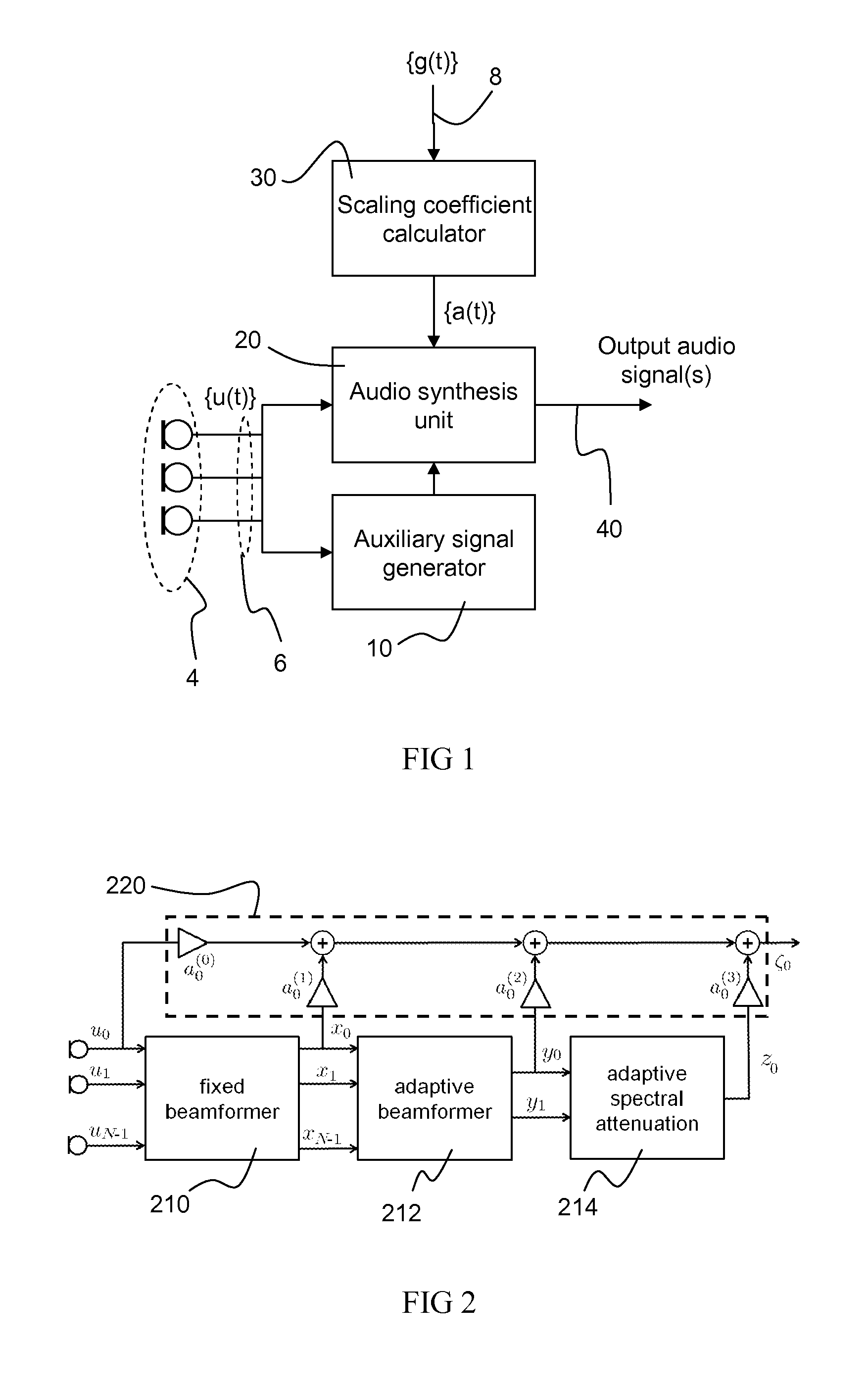
[0098]In the first embodiment the goal is to obtain a monaural (mono) output signal. FIG. 2 shows a block structure for the calculation of the auxiliary signals xn(t), yn(t), and zn(t) required in the algorithm.

[0099]In FIG. 2, the auxiliary signal generator 10 consists of three functional blocks 210, 212, 214:[0100]1) Fixed beamformer 210: the purpose of this block is to perform reweighting of the sound source components of which the source direction is known a priori—that is, the front and back sound sources. The power ratios of these components are altered by the fixed beamformer, both relative to each other and relative to the other sound source components.[0101]2) Adaptive beamformer 212: this block serves to perform reweighting of the localized interfering sound source(s). This necessarily requires an adaptive beamforming algorithm since the interfering sound source direction is unknown.[0102]3) Adaptive spectral attenuation 214: this block reweights the diffuse noise field, b...
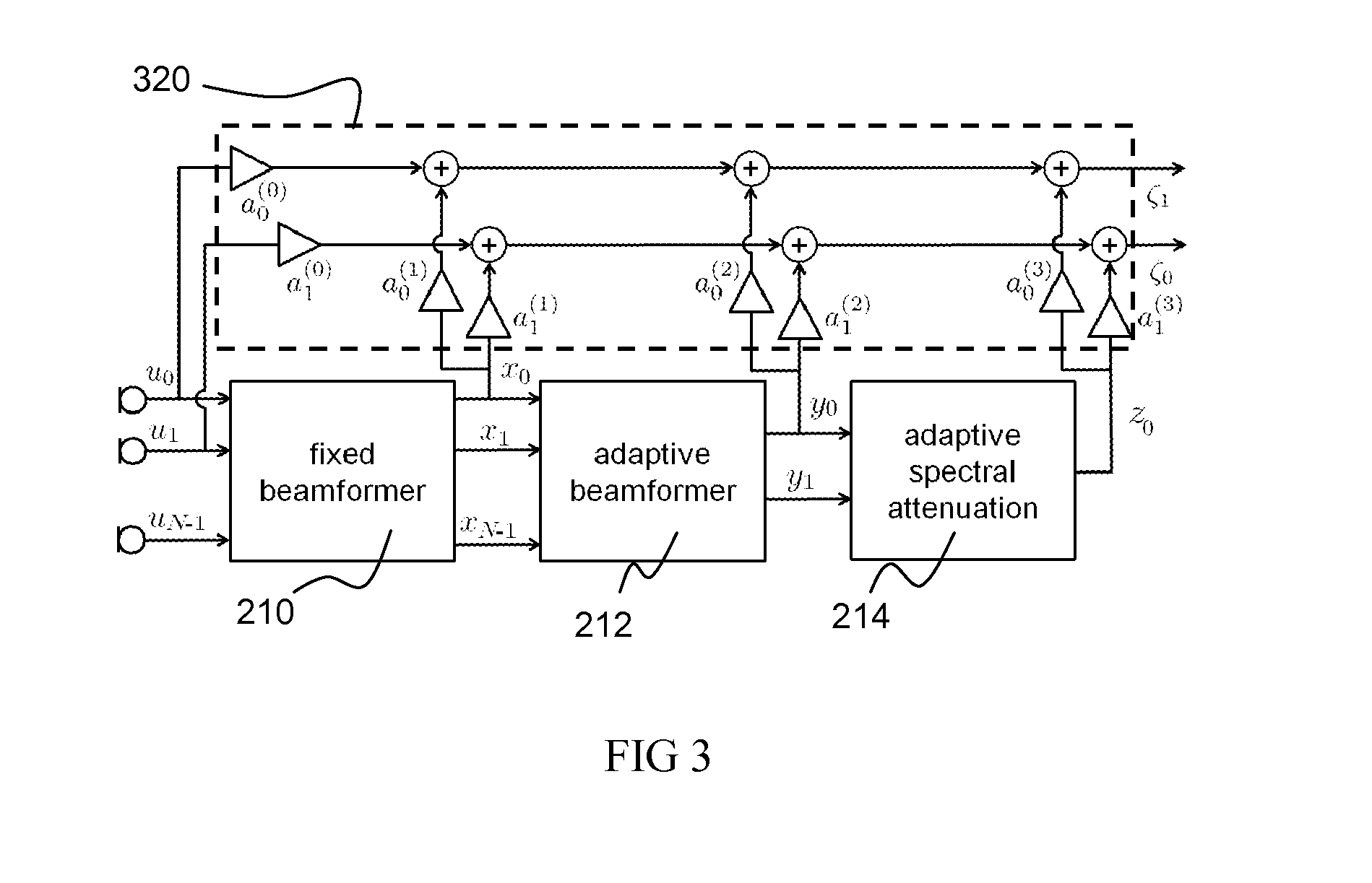
second embodiment

[0106]Instead, in the second embodiment, the block structure shown in FIG. 3 is used for the stereo case. Here, the stereo output signals are calculated as follows:

ζ0(t)=a0(0)(t)u0(t)+a0(1)(t)x0(t)+a0(2)(t)y0(t)+a0(3)(t)z0(t)

ζ1(t)=a1(0)(t)u1(t)+a1(1)(t)x0(t)+a1(2)(t)y0(t)+a1(3)(t)z0(t)

[0107]That is, the same set of auxiliary signals is used for generating both stereo outputs, but a different reference audio signal, un(t), is used in each case. This computation is performed by the audio synthesis unit 320 indicated by the dashed box.

[0108]In the case that N>2 (that is, when the array consists of more than two microphones), one should select u0(t) and u1(t) to be those two microphone signals that are best suited to deliver a stereo image. As will be apparent to those skilled in the art, this will typically depend on the placement of the microphones.

[0109]Note that, due to the particular structure shown in FIG. 5, the weight calculation for the second output signal ζ1(t) should be slig...


PUM


Abstract

An audio-processing device having an audio input, for receiving audio signals, each audio signal having a mixture of components, each corresponding to a sound source, and a control input, for receiving, for each sound source, a desired gain factor associated with the source, by which it is desired to amplify the corresponding component, and an auxiliary signal generator, for generating at least one auxiliary signal from the audio signals, and with a different mixture of components as compared with a reference audio signal; and a scaling coefficient calculator, for calculating scaling coefficients based upon the desired gain factors and upon parameters of the different mixture, each scaling coefficient associated with one of the auxiliary signal and optionally the reference audio signal, and an audio synthesis unit, for synthesizing an output audio signal by applying scaling coefficients to the auxiliary signal and optionally the reference audio signal and combining the results.

Description

[0001]This application claims the priority under 35 U.S.C. §119 of European patent application no. 10012343.9, filed on Sep. 30, 2010, and 10275102.1, filed on Sep. 30, 2010, the contents of which are incorporated by reference herein.FIELD OF THE INVENTION[0002]This invention relates to manipulation of a sound scene comprising multiple sound sources. It is particularly relevant in the case of simultaneous recording of audio by multiple microphones.BACKGROUND OF THE INVENTION[0003]Most existing sound scene manipulation methods operate in a two-stage fashion: in a first stage, the individual sound sources are extracted from one or more microphone recordings; and in a second stage, the separated sound sources are recombined according to the desired sound scene manipulation. When the manipulation consists of a change in the desired level of the individual sound sources (which is commonly the case), the second stage is trivial, once the first stage has been executed. Indeed, the recombin...

Claims


Application Information

Patent Timeline
Patent Type & Authority Applications(United States)
IPC IPC(8): H04R3/00H03G3/00
CPCG10L2021/02166H04R1/406H04R3/005G10L21/0316H04R2499/11H04S2400/15H04S7/30
Inventor VAN WATERSCHOOT, TOONTIRRY, WOUTER JOOSMOONEN, MARC
Owner NXP BV
Why Eureka
Try Eureka