Gas hydrate reactor comprising thermoelectric module

a thermoelectric module and gas hydrate technology, applied in the direction of temperate control, process and machine control, instruments, etc., can solve the problems of inability to provide rapid and accurate temperature control in morphological research, adversely affecting precise analysis, and inability to use conventional gas hydrate reactors, etc., to achieve accurate data

Inactive Publication Date: 2012-04-05
KOREA INST OF IND TECH
View PDF8 Cites 13 Cited by
  • Summary
  • Abstract
  • Description
  • Claims
  • Application Information

AI Technical Summary

Benefits of technology

[0024]Accordingly, the present invention has been made keeping in mind the problems encountered in the related art and the present invention is intended to provide a gas hydrate reactor, which enables the internal temperature of the gas hydrate reactor to be rapidly and precisely controlled, thereby obtaining accurate data necessary for kinetics and phase equilibrium research.
[0026]Also the present invention is intended to provide a gas hydrate reactor, which is able to measure the properties of a gas hydrate within the reactor using a variety of measuring instruments, without the gas hydrate being discharged out of the reactor.
[0034]Also, the controller unit may control a power supply unit for supplying power to the thermoelectric module assembly, thus controlling the temperature of the reactor.

Problems solved by technology

However, because the formation or decomposition of a gas hydrate is accompanied by latent heat and sensible heat, the resulting temperature may fall outside the temperature range required in the experiment, and time delay may occur when controlling such a temperature range, adversely affecting precise analysis.
However, conventional gas hydrate reactors used in such microscopic, macroscopic and morphological research have failed to provide rapid and accurate temperature control.
The conventional gas hydrate reactor as shown in FIG. 1 is problematic because the reactor 4 is located within the water bath 6, making it very difficult to accurately and rapidly control the internal temperature of the reactor in which a gas hydrate is being produced.
Furthermore, because the water bath 6 is filled with water, it is difficult to precisely control the temperature due to the thermodynamic inertia of water.
Even when the temperature of water of the water bath 6 is precisely controlled, the internal temperature of the reactor 4 is indirectly affected by the temperature of the water bath 6, making it impossible to perform rapid and accurate temperature control inside the reactor 4.
Therefore, it is difficult to perform the accurate measurements attributable to such procedures which discharge a gas hydrate out of the reactor and maintain it.

Method used


Image

  • Gas hydrate reactor comprising thermoelectric module
  • Gas hydrate reactor comprising thermoelectric module
  • Gas hydrate reactor comprising thermoelectric module

Examples


Embodiment Construction

[0043]Hereinafter, embodiments of the present invention will be described in detail while referring to the accompanying drawings.

[0044]As used herein, the term “gas” means a guest molecule of a gas hydrate, and the term “water” means a host molecule. In the gas hydrate production, the molecule usable as the guest molecule includes CH4, O2H6, C3H8, CO2, H2, SF6 and so on, and such a guest molecule is referred to as a gas. Also, the host molecule is exemplified by water (H2O).

[0045]Although valves are not shown or described below for the sake of simplification of the drawings, they are preferably located at respective pipes and input ports. In particular, a check valve for backflow prevention and a needle valve for precise control may be used.

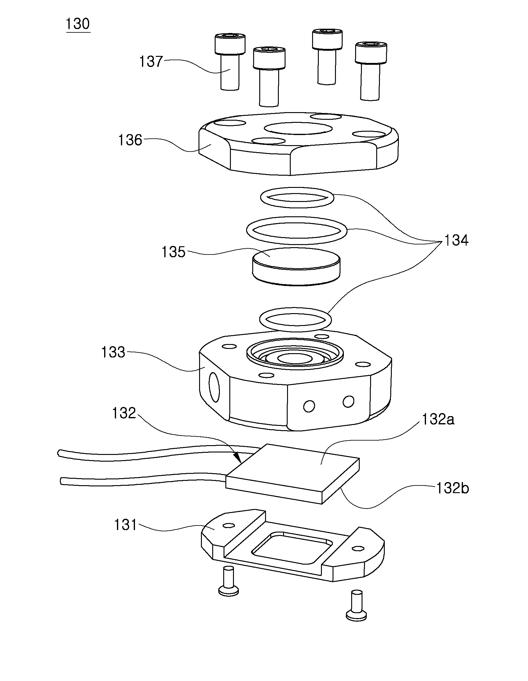
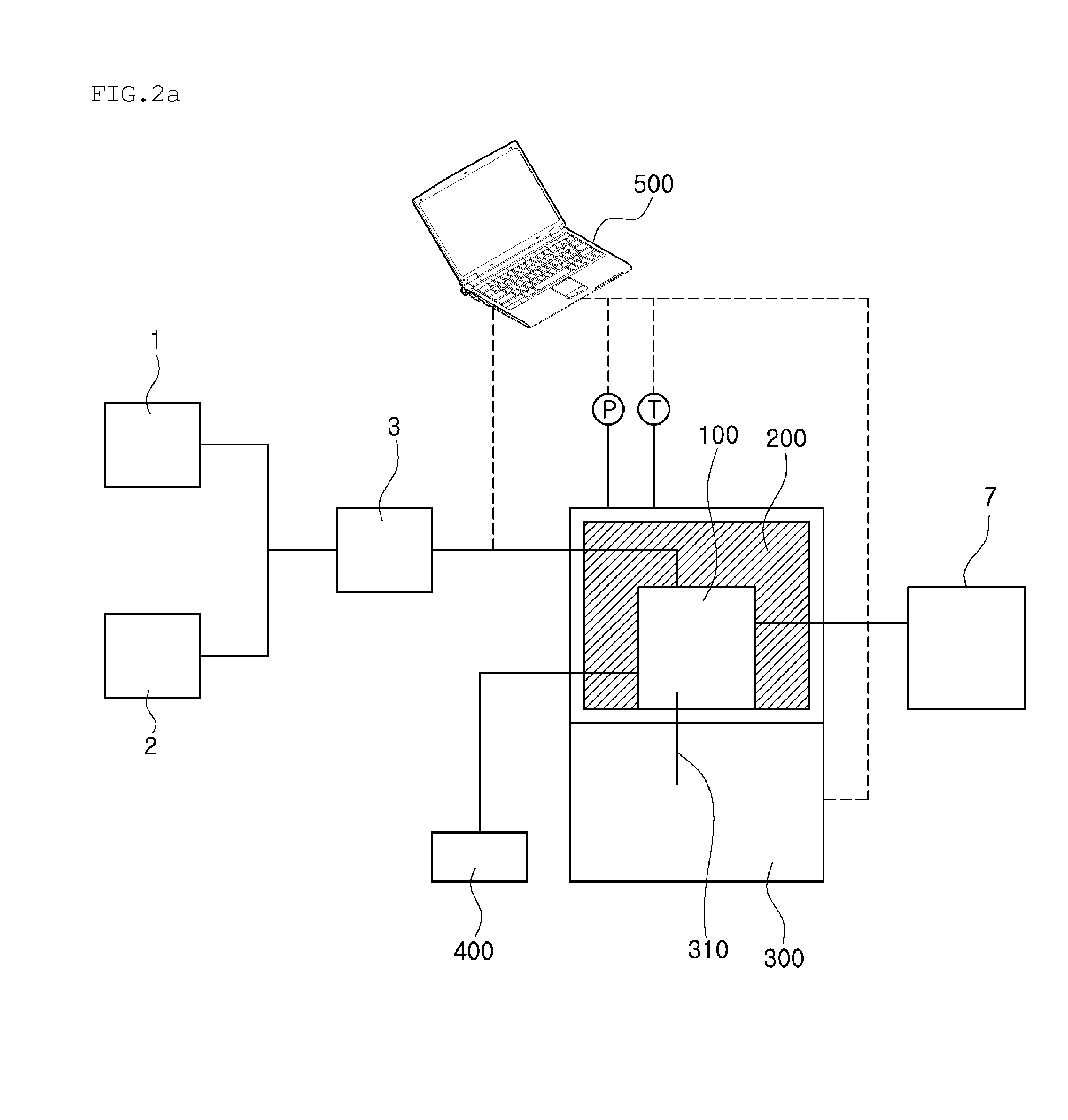
[0046]FIGS. 2A and 2B show a gas hydrate reactor 100 according to the present invention.

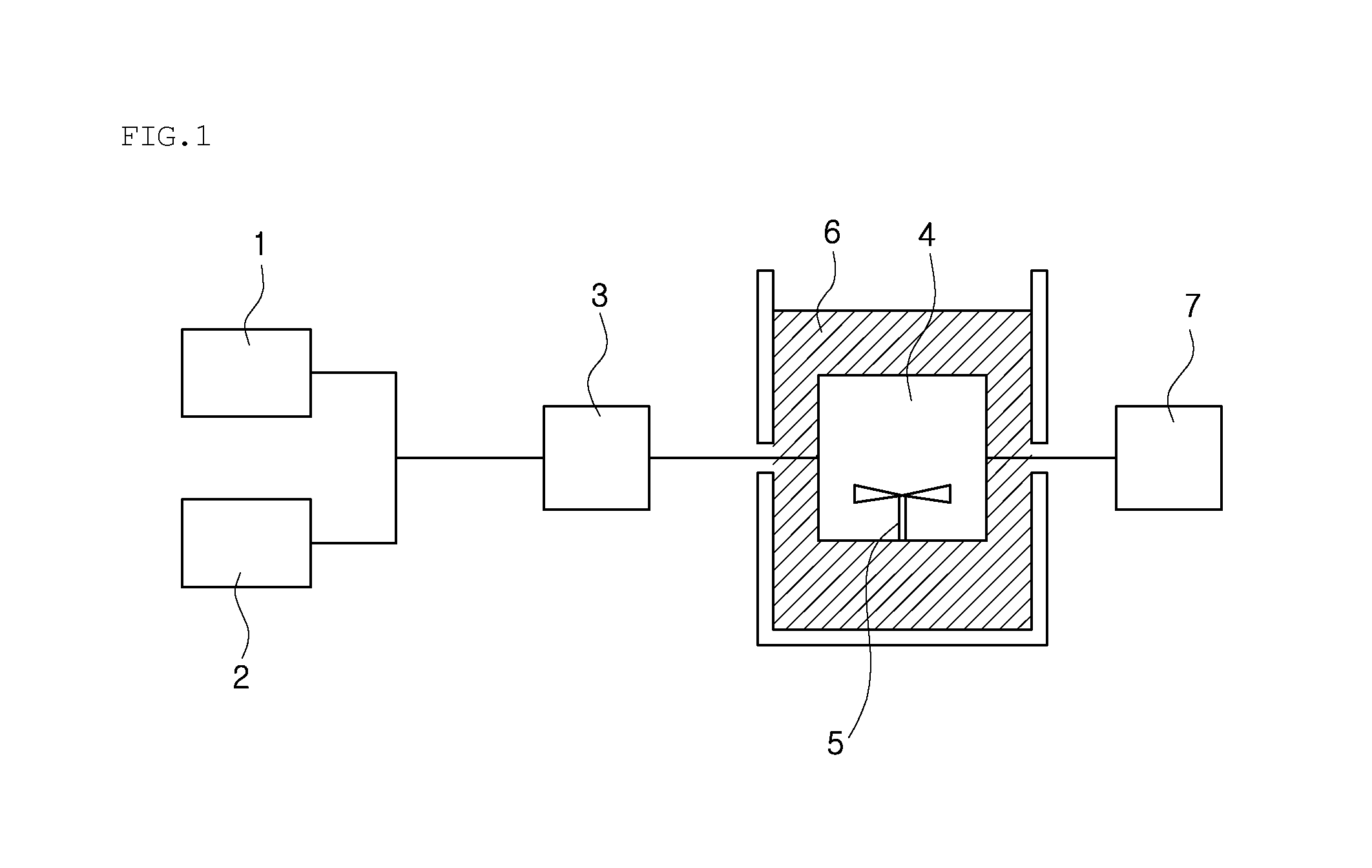
[0047]As in conventional techniques, water and gas are supplied from a water supply unit 1 and a gas supply unit 2, mixed together in a mixing chamber 3 and t...


PUM


Abstract

Disclosed is a gas hydrate reactor including a supply line for supplying water and gas, a thermoelectric module assembly, a front panel including an observation window, and a housing to which the thermoelectric module assembly and the front panel are attached and into which water and gas are supplied using the supply line so that a gas hydrate is formed therein. This reactor enables rapid and precise temperature control, thus allowing accurate data about properties to be easily acquired in kinetics, phase equilibrium, morphology and microscopic (Raman, XRD, etc.) research of a gas hydrate, thereby leading to the discovery of a gas hydrate production / decomposition mechanism and ensuring important information necessary for a gas hydrate application process.

Description

BACKGROUND OF THE INVENTION[0001]1. Technical Field[0002]The present invention relates to a reactor for producing a gas hydrate. More particularly, the present invention relates to a gas hydrate reactor, comprising a supply line for supplying water and gas, a thermoelectric module assembly, a front panel including an observation window, and a housing to which the thermoelectric module assembly and the front panel are attached and into which water and gas are supplied using the supply line so that a gas hydrate is formed therein.[0003]2. Description of the Related Art[0004]A clathrate hydrate or gas hydrate is composed of two components, namely, a host molecule which forms hydrogen-bonded solid lattices and a guest molecule that is captured in the host molecule, and refers to a crystalline compound in which monomers such as methane, ethane, carbon dioxide, etc., are not chemically bonded but are physically captured in a three-dimensional lattice structure formed by hydrogen bonding o...

Claims


Application Information

Patent Timeline
Patent Type & Authority Applications(United States)
IPC IPC(8): G05D23/00B01J19/00
CPCB01J3/006B01J19/24B01J2219/00094G05D23/19B01J2219/00186C10L3/108B01J2219/00135
Inventor LEE, JU DONGLEE, YOUNG CHEOLJO, HYUNG HOCHO, HU-KAB
Owner KOREA INST OF IND TECH
Why Eureka
Try Eureka