Internal-combustion-engine electronic control system

Active Publication Date: 2012-04-12
MITSUBISHI ELECTRIC CORP
View PDF5 Cites 14 Cited by
  • Summary
  • Abstract
  • Description
  • Claims
  • Application Information

AI Technical Summary

Benefits of technology

[0009]The present invention has been implemented in order to solve the problem in the foregoing conventional system; the objective thereof is to prov

Problems solved by technology

As a result, there has been a problem that the time of soft shutoff varies depending on these value

Method used


Image

  • Internal-combustion-engine electronic control system
  • Internal-combustion-engine electronic control system
  • Internal-combustion-engine electronic control system

Examples


embodiment 1

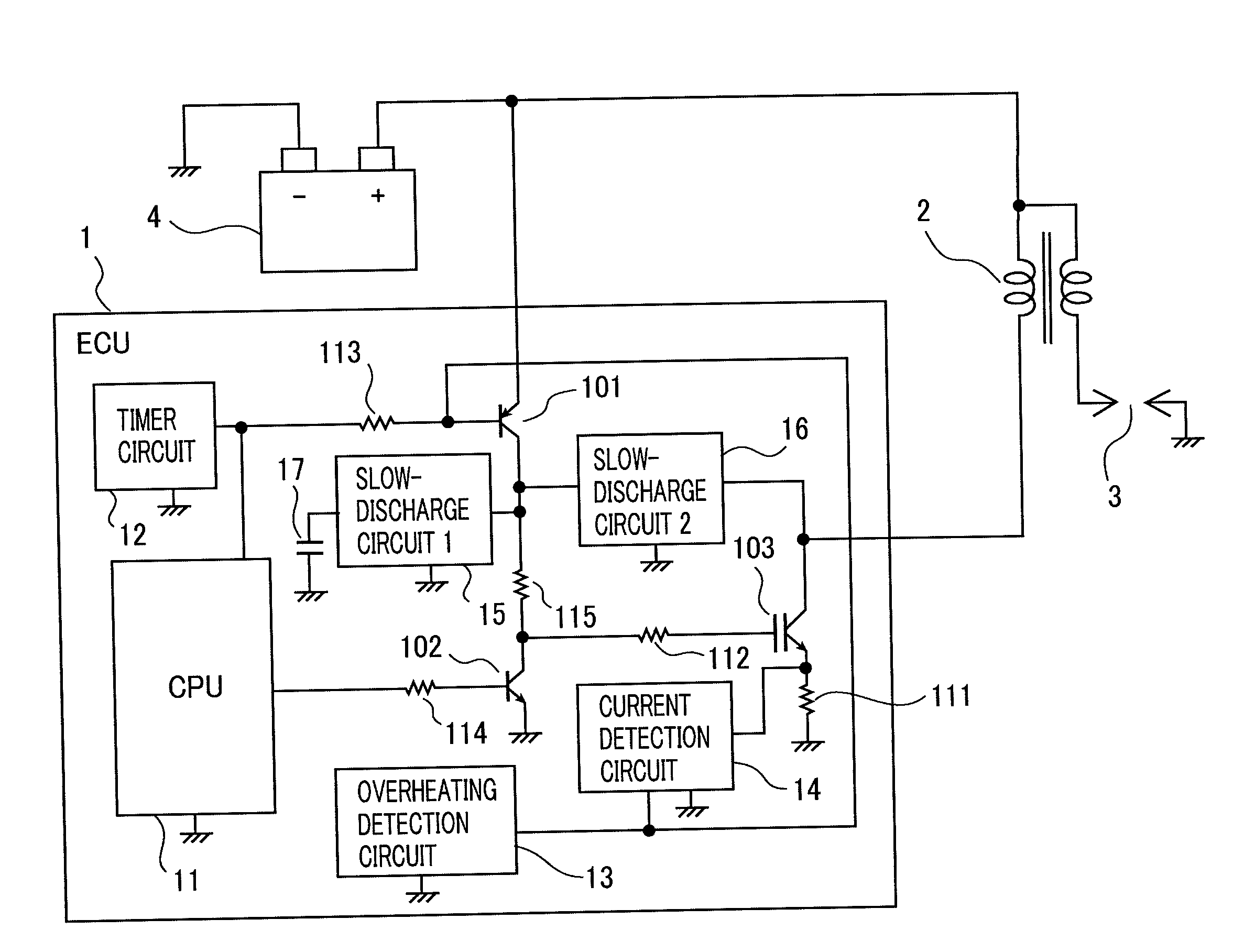
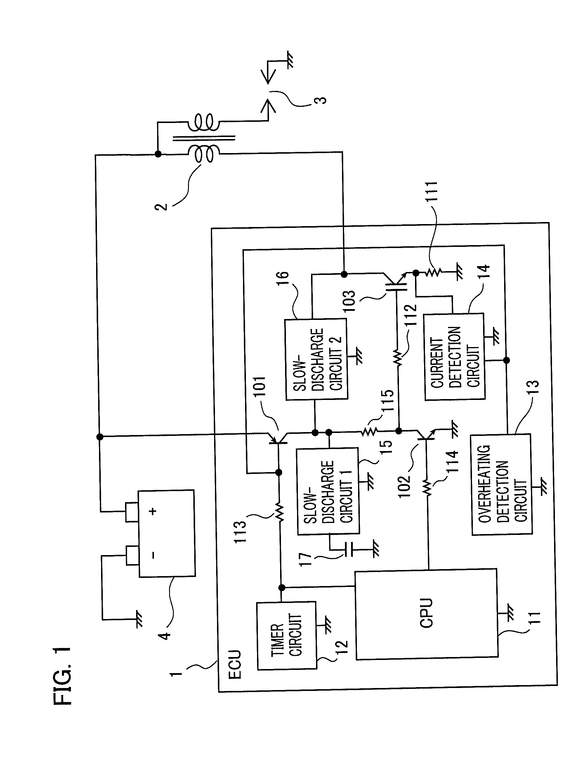
[0024]FIG. 1 is a block diagram of an internal-combustion-engine electronic control system according to Embodiment 1 of the present invention. In FIG. 1, an internal-combustion-engine electronic control system (referred to as an ECU, hereinafter) 1 controls a current that flows in the primary winding of an ignition coil 2. An ignition plug 3 produces a spark discharge by use of a high voltage induced across the secondary winding of the ignition coil 2 so as to ignite a fuel in an unillustrated combustion chamber of an internal combustion engine. A battery 4 supplies electric power to ECU 1 and the ignition coil 2.

[0025]Next, the configuration of ECU 1 will be explained. In ECU 1, the output terminal of a calculation device (referred to as CPU, hereinafter) 11 is connected with the base of an NPN-type transistor 102 by way of a resistor 114. The collector of the transistor 102 is connected with the base or the gate of a power switching device 103 by way of a resistor 112.

[0026]The co...

embodiment 2

[0059]Next, there will be explained an internal-combustion-engine electronic control system according to Embodiment 2 of the present invention. In an internal-combustion-engine electronic control system according to Embodiment 2 of the present invention is characterized in that by use of a timer circuit that determines, based on a change in the engine rotation speed, whether or not energization is being abnormally implemented, by measuring the energization duration of the primary current of an ignition coil, a current detection circuit that detects the primary current flowing in the ignition coil, and a heat detection circuit that detects abnormal heating, the operation status of the power switching device is recognized, the time constant for capacitor slow discharge operation is selected, and then the power switching device is softly shut off.

[0060]FIG. 5 is a block diagram of an internal-combustion-engine electronic control system according to Embodiment 2 of the present invention...

embodiment 3

[0079]Next, there will be explained an internal-combustion-engine electronic control system according to Embodiment 3 of the present invention. In Embodiment 3, by combining a slow-discharge circuit with a current limiting circuit, for limiting the primary current flowing in the ignition coil, that is a circuit for suppressing the secondary voltage from making the ignition plug produce a spark discharge when energization of the ignition coil is started, the signal outputted from the power switching device is suppressed from oscillating when the primary current is limited.

[0080]FIG. 7 is a block diagram of an internal-combustion-engine electronic control system according to Embodiment 3 of the present invention.

[0081]The current detection resistor 111 connected with the emitter or the source of the power switching device 103 converts the primary current of the ignition coil 2 into a voltage; when this voltage exceeds a reference voltage (Vth) 132 of an operational amplifier 131, the ...


PUM


Abstract

An internal-combustion-engine electronic control system according to the present invention is provided with a power switching device that applies or shuts off a primary current of an ignition coil of an internal combustion engine so that at the secondary side of the ignition coil, there is generated a voltage for making an ignition plug of the internal combustion engine produce a spark discharge; and a control unit that turns on or off the power switching device. The internal-combustion-engine electronic control system is characterized in that the control unit is provided with a circuit unit that makes the power switching device softly shut off so as to prevent the ignition plug from producing the spark discharge, and in accordance with the characteristics of the power switching device, the control unit changes the characteristics of the soft shutoff halfway through the shutoff operation.

Description

BACKGROUND OF THE INVENTION[0001]1. Field of the Invention[0002]The present invention relates to an internal-combustion-engine electronic control system and particularly to an electronic control system that controls an internal-combustion-engine ignition device.[0003]2. Description of the Related Art[0004]As is well known, in an internal-combustion-engine ignition device, for example, in the case where an ignition signal is inputted for a time longer than a predetermined time, in the case where an electronic component included in the ignition device overheats, or in the case where an excessive current flowing in an ignition coil is detected, it is required to forcibly shut off the primary current of the ignition coil at a timing different from the regular ignition timing so as to protect the ignition device.[0005]However, in the case where the primary current of an ignition coil is forcibly shut off at a timing different from the regular ignition timing, it is required to softly shu...

Claims


Application Information

Patent Timeline
IPC IPC(8): F02P3/045
CPCF02P3/0442F02P11/00F02P9/002
Inventor MIZUKAMI, HIROSHINOBE, HISANORIIKEDA, TORUSERA, YOSHIYUKI
Owner MITSUBISHI ELECTRIC CORP
Why Eureka
Try Eureka