Unlock instant, AI-driven research and patent intelligence for your innovation.

Power semiconductor device current detector circuit and detection method

a current detector and semiconductor device technology, applied in the direction of current measurement, power supply testing, instruments, etc., can solve the problems of affecting the detection effect of current detectors, so as to reduce the loss of current detectors, improve the accuracy of main current calculation, and correct the sense characteristics

Active Publication Date: 2012-04-12
FUJI ELECTRIC CO LTD
View PDF10 Cites 7 Cited by
  • Summary
  • Abstract
  • Description
  • Claims
  • Application Information

AI Technical Summary

Benefits of technology

[0024]Bearing in mind the problems of the related art, the invention has an object of solving at least the three problems shown below. That is,1. to reduce an increase in size and increase in loss of the current detector when using a direct current current transformer (DCCT) or shunt resistor (for detecting the main current).2. To ensure that no decrease in current detection accuracy occurs when utilizing a sensing function-equipped power semiconductor device.3. To achieve a digital control of a correction circuit that improves the current detection accuracy of the sensing function-equipped power semiconductor device, and a suppression of the circuit scale.
[0025]More specifically, the object is at least toa: to realize a small current detector circuit with low loss by detecting current using the sensing function of a sensing function-equipped power semiconductor device.b: In this case, to correct the linearity of the main current Im and sense current Is, and improve the current detection accuracy.c: To enable a digital control of a correction circuit that corrects the linearity, with a realizable circuit scale.
[0028]Also, the current detector circuit is configured in such away that a parameter Kg that corrects a difference in internal resistance, and a parameter Ko that corrects a difference in internal threshold voltage, are set as correction parameters for improving the current detection accuracy of the semiconductor device, and the parameters can be changed from the exterior by a digital signal passing through a serial or parallel signal supply unit.
[0030]According to the invention, it is possible to correct the sense characteristics of a sensing function-equipped power semiconductor device, and a highly accurate main current calculation is possible utilizing the sensing function. As the main current detection is carried out using the sensing function in this way, it is possible to realize a miniaturization and decrease in loss of the current detector when compared with the heretofore known methods using a direct current current transformer (DCCT) or shunt resistor (for detecting the main current).
[0031]Also, according to the invention, as the setting of the correction parameters can be carried out from the exterior using a serial or parallel signal supply unit, it is possible to realize an application circuit in which the current detector circuit of the invention is mounted in an appropriate circuit scale.
[0032]Also, by applying the current detector circuit of the invention in the lower arm of an inverter device or the lower arm of a chopper circuit, it is possible to accurately detect the output current of the inverter device or chopper circuit.

Problems solved by technology

That is, with the current detection method in which a DCCT is used shown in FIG. 9, there are problems in that the price is generally high because the DCCT uses a Hall sensor and a core, and that the output characteristics of the DCCT change due to the ambient temperature.
Also, there is a problem in that the size of the detector increases because a core is used, and this restricts the miniaturization of the power conversion device.
Also, with the current detection method in which a shunt resistor is used shown in FIG. 10, there is a problem in that, as power loss occurs due to the shunt resistor, the power conversion efficiency of the power conversion device decreases.
Furthermore, there is a problem in that the size of the resistor itself increases in order to tolerate a large loss, and this restricts the miniaturization of the conversion device.
However, with this method, current detecting accuracy is a problem.
However, as the accuracy is low, the method using the sensing region cannot be put to practical use.
However, as there is actually variation in the characteristics, the ratio between the main current and sense current is not constant.

Method used


Image

  • Power semiconductor device current detector circuit and detection method
  • Power semiconductor device current detector circuit and detection method
  • Power semiconductor device current detector circuit and detection method

Examples


Embodiment Construction

[0047]Hereafter, a detailed description will be given of an embodiment of the invention.

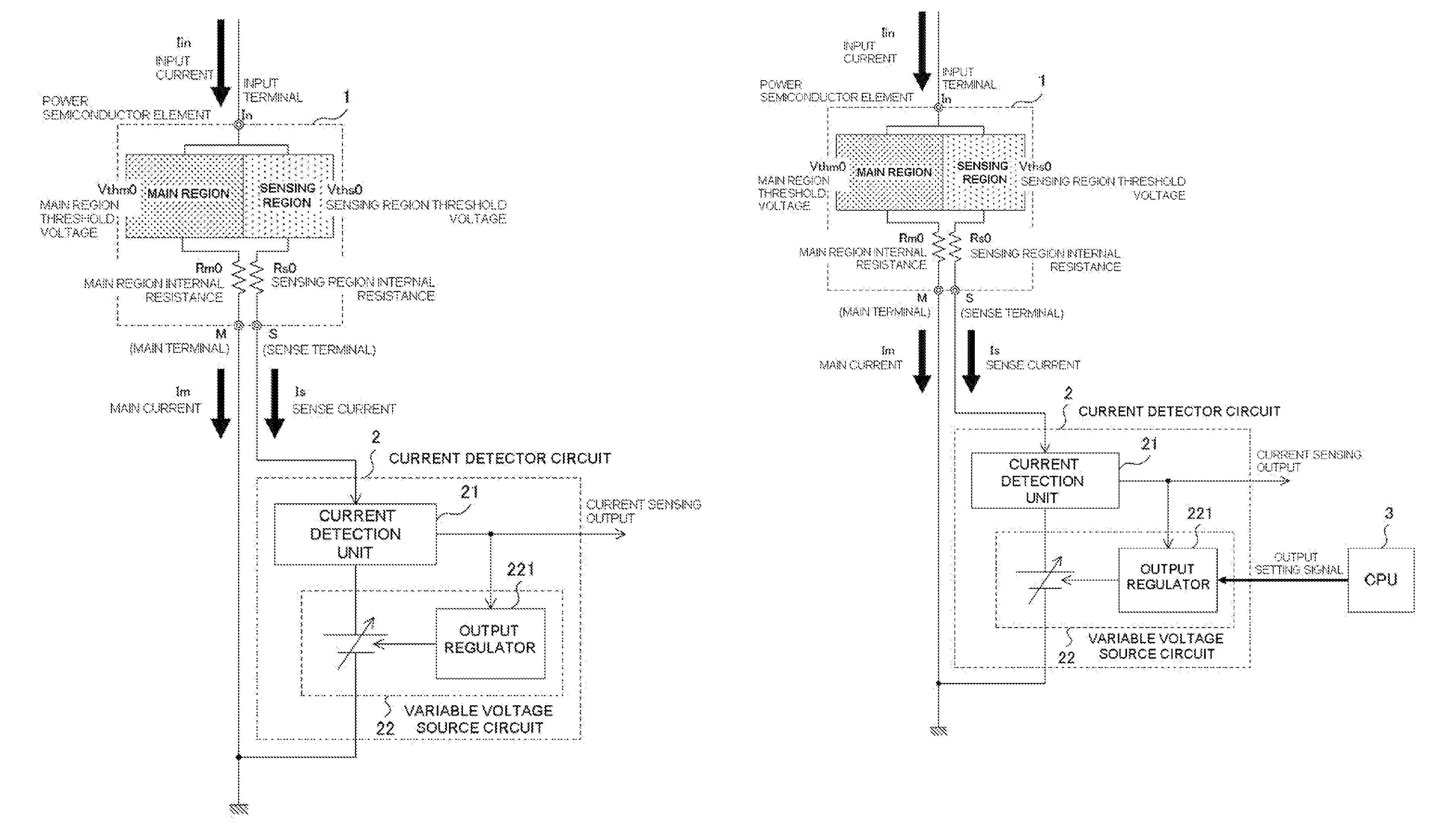
[0048]A configuration principle of a power semiconductor device current detector circuit of the invention, taking the difference in characteristics between a main region and sensing region to be due to the difference between a threshold voltage and internal resistance of each IGBT, is that the current detector circuit is configured in such a way as to correct the difference between the threshold voltage and internal resistance of each IGBT. Specifically, the current detector circuit is configured in such a way that an already known current is caused to flow through the main region, the current is detected from a sense terminal, and a gain and offset are regulated in order to correct the difference in characteristics between the main region and sensing region in accordance with the detected current. More specifically, the current detector circuit is configured in such a way that an already known c...


PUM


Abstract

A small power semiconductor device current detector circuit and detection method with low loss by detecting current using the sensing function of a power semiconductor device is disclosed. An already known current is caused to flow through a main region of the power semiconductor device. The current is detected by a current detector unit connected to a sense terminal of the power semiconductor device. A deviation in characteristics between the main region and a sensing region is detected by a variable voltage source circuit based on the detected current. An offset amount and gain amount in an output regulator are regulated in such a way that the characteristics of the two coincide. The offset amount and gain amount to be regulated may be supplied to the output regulator, serially or in parallel, from a CPU provided externally.

Description

BACKGROUND OF THE INVENTION[0001]1. Technical Field[0002]The present invention relates to a power semiconductor device current detector circuit and detection method, and in particular, relates to a current detector circuit and detection method that detect a current flowing through a power semiconductor device such as a diode, thyristor, transistor (bipolar transistor or metal oxide semiconductor field effect transistor (MOSFET)), or insulated gate bipolar transistor (IGBT).[0003]2. Related Art[0004]An IGBT module in which are mounted an IGBT, which is one kind of power semiconductor device, and a free wheeling diode (hereafter called an FWD) is applied to a power conversion device such as an inverter or direct current (DC) chopper circuit.[0005]Generally, an output current detection is necessary in order to control these power conversion circuits. Normally, two methods are widely employed in the output current detection, which are1: a method using a current detector such as a curren...

Claims


Application Information

Patent Timeline
IPC IPC(8): G05F3/02
CPCG01R19/0092G01R31/42G01R31/2607
Inventor UEMURA, HIROFUMI
Owner FUJI ELECTRIC CO LTD