
Reduction of Recirculation in Catheters

a technology of recirculation and catheter, which is applied in the field of recirculation reduction of catheter recirculation, can solve the problems of occlusion of the lumen opening, thrombosis, and high shear stress around the fluid entry point, and achieve the effect of reducing the outflow velocity of fluid and preventing fluid jetting

Active Publication Date: 2012-04-12
CR BARD INC
View PDF7 Cites 9 Cited by
  • Summary
  • Abstract
  • Description
  • Claims
  • Application Information

AI Technical Summary

Benefits of technology

"The patent describes a catheter with a distal tip designed to decrease the outflow velocity of fluid being delivered through the catheter. This is achieved by various methods such as providing side holes or an enlarged cross-sectional area at the distal end of the catheter. The low outflow profile catheter tip reduces the disruption on the existing circulatory flow within the patient's body and minimizes the mixing of blood being infused with the existing vein blood. The design also reduces the likelihood of thrombus formation and occlusion of the catheter. The patent also describes a dual lumen hemodialysis catheter with staggered ports to prevent blood being infused through the outflow port being recaptured by the suction at the inflow port. The invention is useful in various medical applications where a catheter with low outflow profile is desired."

Problems solved by technology

This tends to cause high shear stress around the fluid entry point.
In a traditional “staggered dual-D” design catheter, this high stress at the fluid entry point may lead to the formation of thrombosis.
The thrombus formation may result in the occlusion of the lumen opening and reducing the effective life of the catheter.

Method used


Image

  • Reduction of Recirculation in Catheters
  • Reduction of Recirculation in Catheters
  • Reduction of Recirculation in Catheters

Examples


Embodiment Construction

[0023]The following detailed description should be read with reference to the drawings, in which like elements in different drawings are identically numbered. The drawings, which are not necessarily to scale, depict selected preferred embodiments and are not intended to limit the scope of the invention. The detailed description illustrates by way of example, not by way of limitation, the principles of the invention. This description will clearly enable one skilled in the art to make and use the invention, and describes several embodiments, adaptations, variations, alternatives and uses of the invention, including what is presently believed to be the best mode of carrying out the invention.

[0024]Before describing the present invention, it is to be understood that unless otherwise indicated this invention need not be limited to applications in human. As one of ordinary skill in the art would appreciate, variation of the invention may be applied to other mammals as well. Moreover, whil...


PUM


Abstract

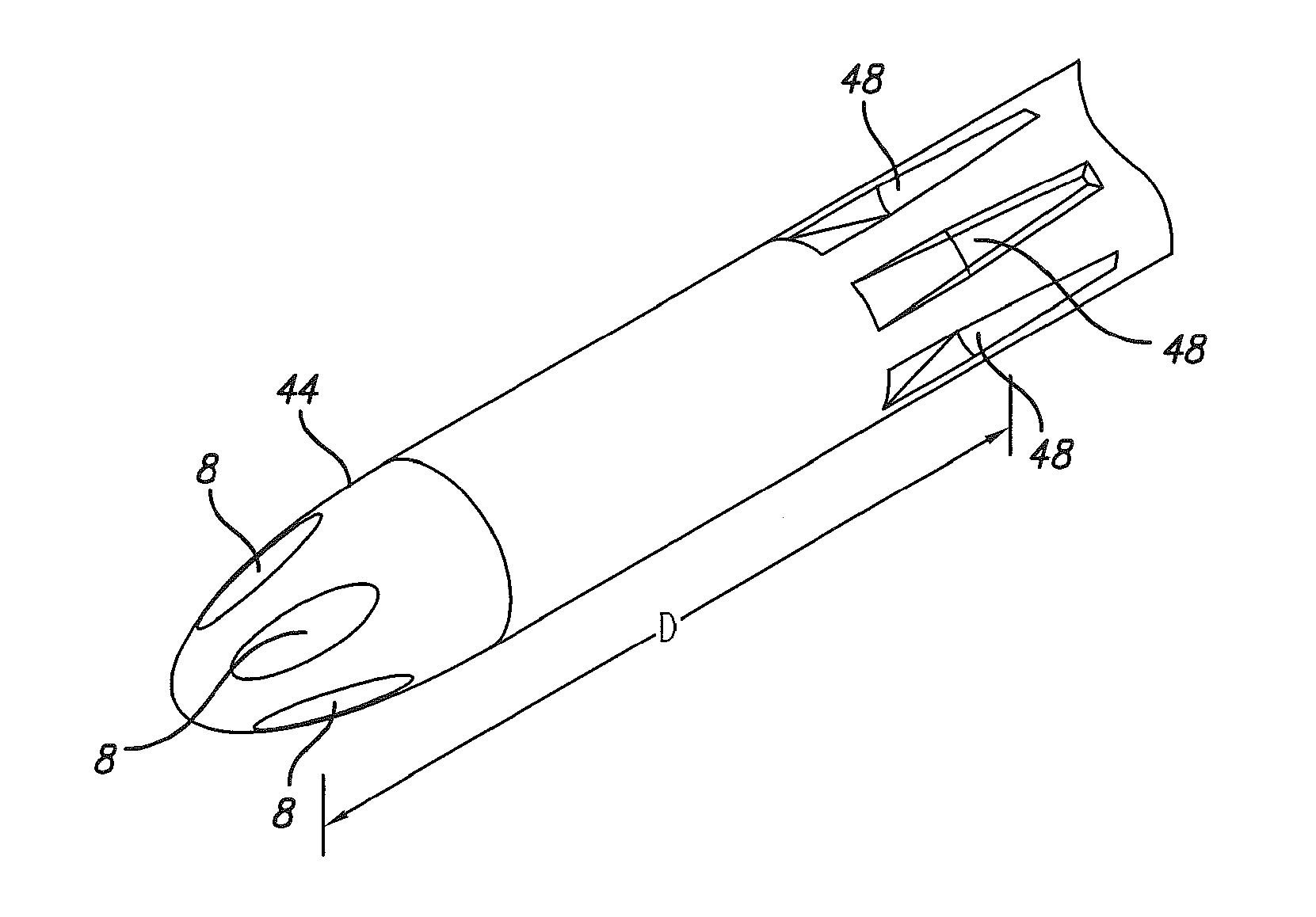
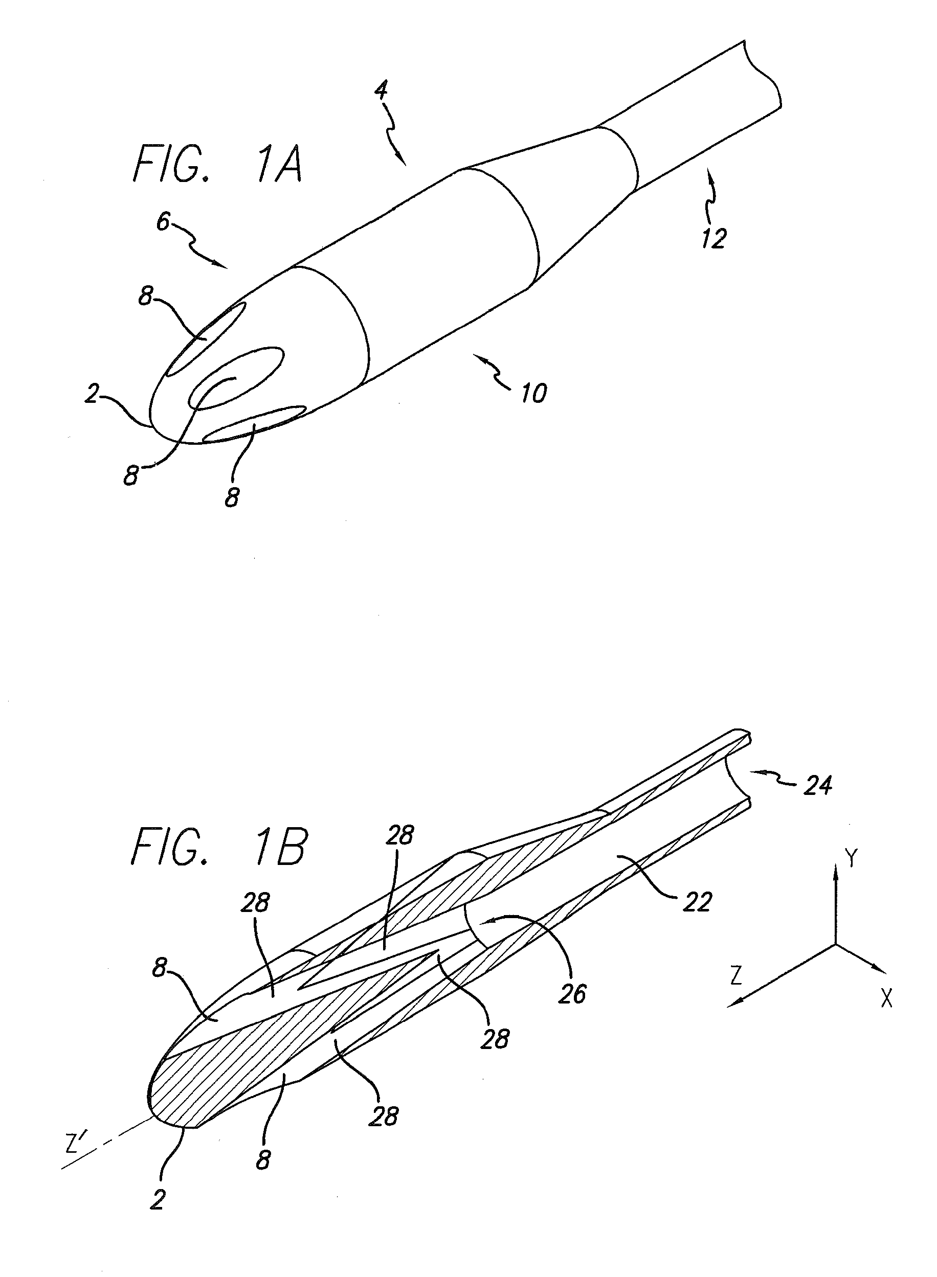
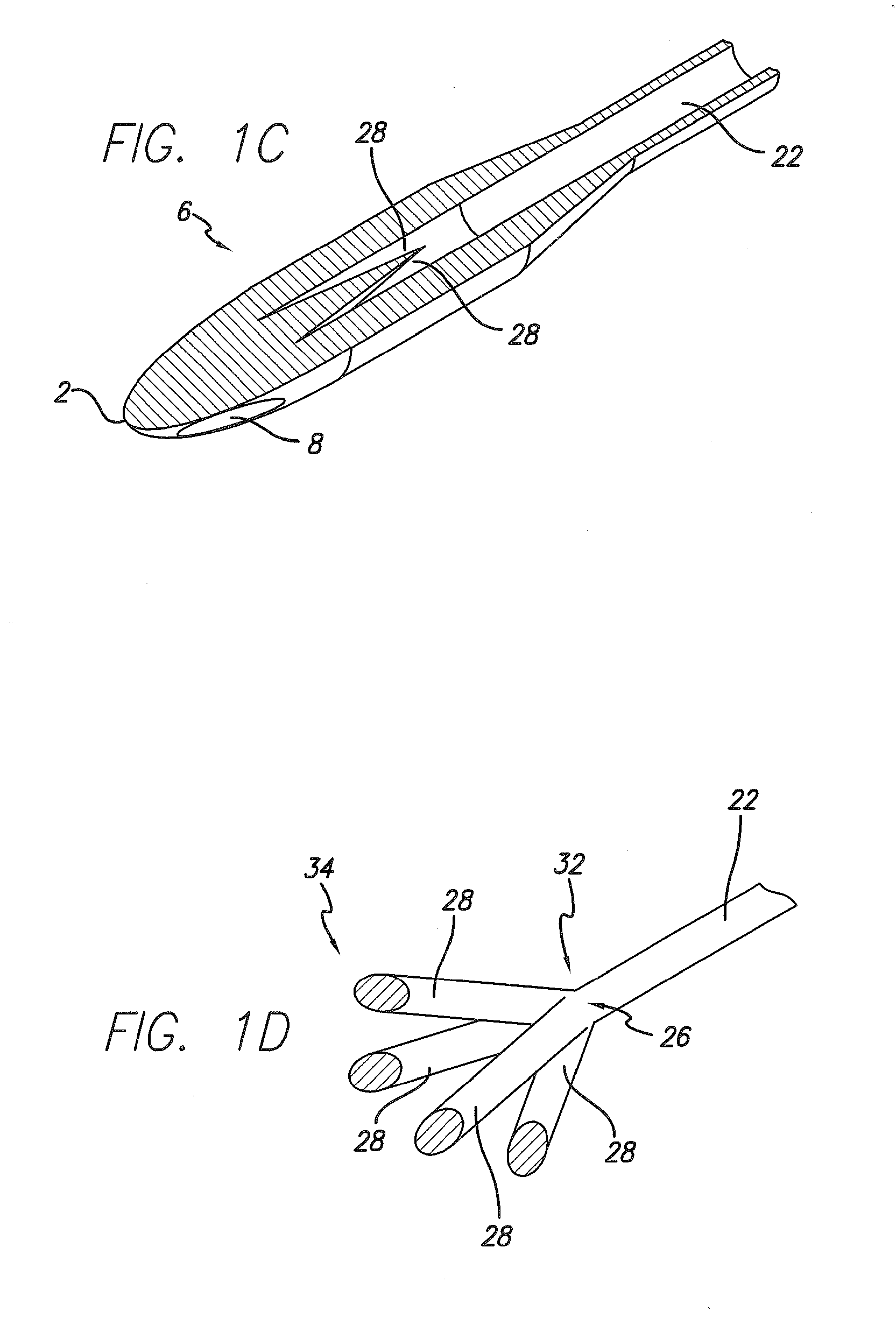
A catheter tip designed to reduce the outflow velocity and / or directional momentum of fluid being infused by a catheter having such a tip. In one variation, a plurality of channels is provided at the distal portion of the catheter to increase the outflow cross-sectional area. In another variation, the diameter of the catheter at its distal portion where the fluid exits is increased. In yet another variation, a bullet-shaped nose is implemented which may decrease turbulence at the distal end of catheter tip. The low velocity outflow catheter tip may also be implemented on a dual lumen catheter, such as a hemodialysis catheter, to reduce recirculation rate. Various device configurations and methods for such implementations are also disclosed.

Description

CROSS-REFERENCE TO RELATED APPLICATIONS[0001]This application is a division of U.S. patent application Ser. No. 10 / 883,934, filed Jul. 2, 2004, which is incorporated by reference in its entirety into this application.BACKGROUND OF THE INVENTION[0002]In various medical situations there is a need to divert blood from the circulatory system and then later reintroduce the removed blood back into the circulatory system. For example, patients with renal problems may require hemodialysis to stay alive. In such a situation, due to the fact that the patient's kidney is not functioning properly to remove biological waste from the patient's circulatory system, the blood must be removed from the patient and treated outside the body to remove the biological wastes, and then returned to the circulatory system. A common approach is to introduce a dual lumen catheter into a blood vessel within the patient's body. The catheter has one lumen for removing blood and another lumen for reintroducing the ...

Claims


Application Information

Patent Timeline
Patent Type & Authority Applications(United States)
IPC IPC(8): A61M25/14
CPCA61M25/0071A61M2025/0073A61M2206/14A61M25/0068
Inventor DIFIORE, ATTILIO E.TRIPLETT, DANIEL J.
Owner CR BARD INC
Learn More