Microwave plasma source and plasma processing apparatus

a plasma processing apparatus and plasma technology, applied in the direction of plasma technique, electrical apparatus, electric discharge tubes, etc., can solve the problems of non-uniform plasma density distribution, process complexity, and inability to uniformize the plasma density distribution, so as to improve the in-plane uniformity of electric field intensity and uniform plasma process

Inactive Publication Date: 2012-04-19
TOKYO ELECTRON LTD
View PDF9 Cites 24 Cited by
  • Summary
  • Abstract
  • Description
  • Claims
  • Application Information

AI Technical Summary

Benefits of technology

[0017]In accordance with the present disclosure, the phases of the microwaves may be adjusted by fixing the input phase of the microwave inputted to one of two adjacent microwave introducing devices while varying the input phase of the microwave inputted to the other microwave introducing device according to the periodic waveform. Alternatively, the phases of the microwaves may be adjusted by varying input phases of the microwaves inputted to both of the two adjacent microwave introducing devices according to periodic waveforms not overlapped with each other. Accordingly, by continuously changing the positions of the nodes and the antinodes of the standing wave generated when the microwaves are radiated into the processing chamber, it may be possible to uniformize electric field intensity and to improve in-plane uniformity of the electric field intensity. As a result, an electron density, i.e., a plasma density within the processing chamber can be uniformized, and a uniform plasma process can be performed.

Problems solved by technology

In this case, processes become more complicated.
The antinodes and the nodes of the standing wave may cause non-uniformity of an electron density distribution in the plasma.
As a result, a plasma density distribution may not become uniformized.

Method used


Image

  • Microwave plasma source and plasma processing apparatus
  • Microwave plasma source and plasma processing apparatus
  • Microwave plasma source and plasma processing apparatus

Examples


first embodiment

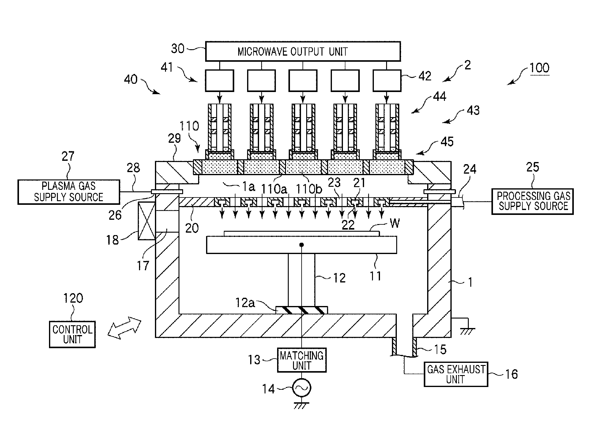
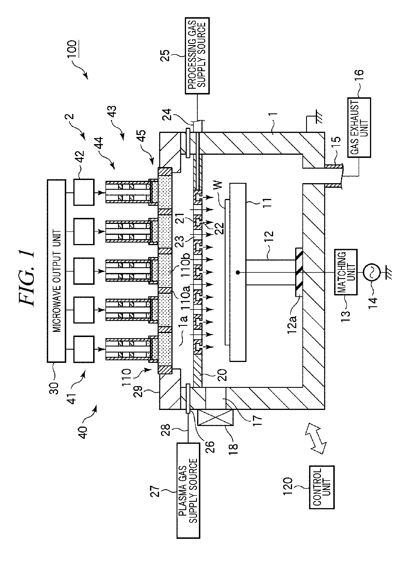
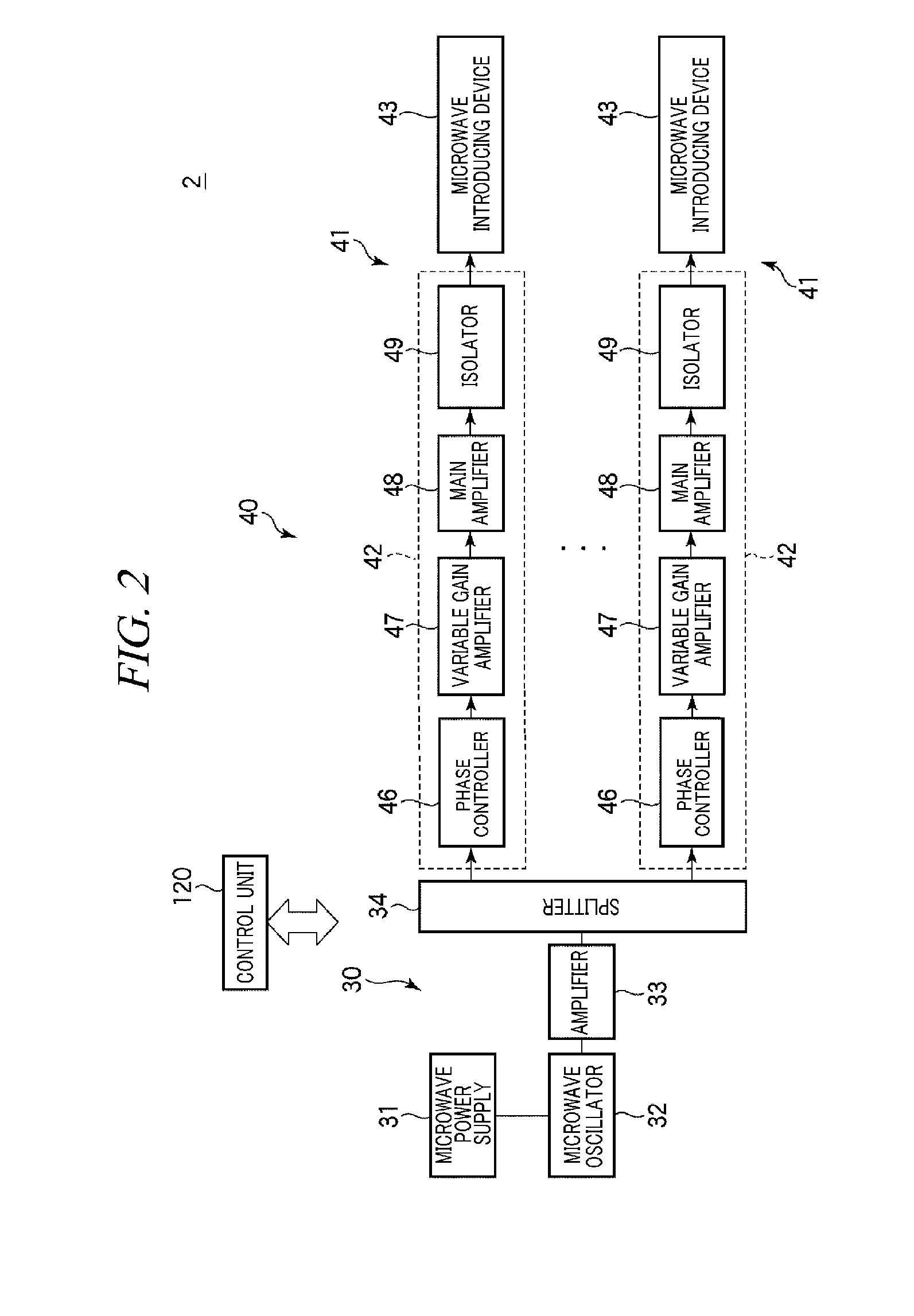
[0035]FIG. 1 is a cross sectional view illustrating a schematic configuration of a surface wave plasma processing apparatus having a microwave plasma source in accordance with a first embodiment of the present disclosure. FIG. 2 is a configuration view of the microwave plasma source. FIG. 3 is a plane view schematically illustrating a microwave supply unit of the microwave plasma source. FIG. 4 shows an example circuit configuration of a main amplifier of an antenna module of the microwave plasma source. FIG. 5 is a cross sectional view illustrating a microwave introducing device of the antenna module of the microwave plasma source. FIG. 6 is a transversal cross sectional view taken along a line AA′ of FIG. 5, and shows a power supply unit of the microwave introducing device. FIG. 7 is a transversal cross sectional view taken along a line BB′ of FIG. 5, and shows a slug and a sliding member of a tuner.

[0036]A surface wave plasma processing apparatus 100 is configured as a plasma etc...

second embodiment

[0084]Now, a second embodiment of the present disclosure will be described.

[0085]Although basic configurations of a microwave plasma source and a plasma processing apparatus in accordance with the second embodiment are the same as those of the first embodiment, a ceiling plate has a different configuration.

[0086]FIG. 12 illustrates a plane view schematically illustrating a ceiling plate and a microwave introducing device of a microwave plasma source in accordance with the second embodiment. FIG. 13 is a cross sectional view taken along a line CC′ of FIG. 12. As shown in FIGS. 12 and 13, a circular ceiling plate 110 in accordance with the second embodiment includes dielectric members 110b fitted to positions where a multiple number of microwave introducing devices 43 for radiating microwaves into the chamber 1 are provided. Each dielectric member 110b is made of a dielectric material such as quartz and has a hexagon shape. Adjacent dielectric members 110b are placed close to each oth...


PUM

PropertyMeasurementUnit
frequencyaaaaaaaaaa
frequencyaaaaaaaaaa
frequencyaaaaaaaaaa

Abstract

There are provided a microwave plasma source and a plasma processing apparatus capable of improving uniformity of a plasma density distribution within a processing chamber by controlling positions of nodes and antinodes of a standing wave of microwave within the processing chamber not to be fixed. The microwave plasma source 2 includes a microwave supply unit 40. The microwave supply unit 40 includes multiple microwave introducing devices 43 each introducing microwave into the processing chamber; and multiple phase controllers 46 for adjusting phases of the microwaves inputted to the microwave introducing devices 43. Here, the phases of the microwaves inputted to the microwave introducing devices 43 are adjusted by fixing an input phase of the microwave inputted to one of two adjacent microwave introducing devices 43 while varying an input phase of the microwave inputted to the other microwave introducing device 43 according to a periodic waveform.

Description

CROSS-REFERENCE TO RELATED APPLICATION[0001]This application claims the benefit of Japanese Patent Application No. 2010-234688 filed on Oct. 19, 2010, the entire disclosures of which are incorporated herein by reference in their entirety.FIELD OF THE INVENTION[0002]The present disclosure relates to a microwave plasma source and a plasma processing apparatus using the same.BACKGROUND OF THE INVENTION[0003]In a manufacturing process of a semiconductor device or a liquid crystal display, a plasma processing apparatus such as a plasma etching apparatus or a plasma CVD apparatus has been used for performing a plasma process such as an etching process or a film forming process on a processing target substrate such as a semiconductor wafer or a glass substrate.[0004]Recently, as such a plasma processing apparatus, a RLSA (Radial Line Slot Antenna) microwave plasma processing apparatus capable of uniformly generating high-density surface wave plasma having a low electron temperature is attr...

Claims


Application Information

Patent Timeline
Patent Type & Authority Applications(United States)
IPC IPC(8): C23F1/08
CPCH01J37/32293H05H2001/463H05H1/46H05H1/463H01L21/3065H01L21/205
Inventor IKEDA, TAROOSADA, YUKI
Owner TOKYO ELECTRON LTD
Why Eureka
Try Eureka