Brake system for a vehicle and method for operating a brake system for a vehicle

a brake system and vehicle technology, applied in the direction of braking systems, rotary clutches, fluid couplings, etc., can solve the problems of unsatisfactory braking input by the driver, etc., to achieve easy cover, free travel distance, and small installation space requirements of the spring devi

Inactive Publication Date: 2012-04-19
ROBERT BOSCH GMBH
View PDF9 Cites 12 Cited by
  • Summary
  • Abstract
  • Description
  • Claims
  • Application Information

AI Technical Summary

Benefits of technology

[0010]Another advantage of the present invention is that the “free travel distance” achieved by the spring device is easily covered by the driver operating the brake activation element for at least the minimum actuator travel distance. Thus, with a reasonable effort the driver is able to directly brake the piston-cylinder unit, for example a master brake cylinder.
[0011]One significant advantage of the spring device over a brake booster is that the spring device does not require the provision of energy. In addition, the installation space requirements of the spring device are comparatively small.
[0012]Furthermore, in the present invention the first brake booster is usable for building up a hydraulic braking torque as a supplement or an alternative to a generator braking torque when transmission of braking force by the driver is prevented. Thus, for example, an excessively low generator braking torque may be compensated for by building up the hydraulic braking torque with the aid of the first brake booster, so that a desired overall braking torque, preferably corresponding to operation of the brake activation element by the driver, is maintained. In addition, in situations in which it is advantageous to not use the generator, instead of the generator braking torque the hydraulic braking torque may be built up with the aid of the first brake booster. In the present invention, for building up the hydraulic braking torque it is not necessary in these situations to close isolation valves and / or to activate pumps of the hydraulic braking circuit. This has the advantage that the hydraulic braking torque may be built up comparatively quickly and easily. Since building up the hydraulic braking torque also does not require uncustomary use of a component of the hydraulic brake system, the brake system described here may thus be equipped with a plurality of brake circuits or various types of hydraulic brake circuit components. The brake system described here thus simplifies alternation of its hydraulic components.

Problems solved by technology

Thus, when the brake activation element is operated in this way, the vehicle may be decelerated with the aid of an electric and / or magnetic (nonhydraulic) braking device, in particular a regenerative braking device such as a generator, for example, without this resulting in an undesired exceedance of the intended braking input by the driver.
In addition, the installation space requirements of the spring device are comparatively small.

Method used


Image

  • Brake system for a vehicle and method for operating a brake system for a vehicle
  • Brake system for a vehicle and method for operating a brake system for a vehicle
  • Brake system for a vehicle and method for operating a brake system for a vehicle

Examples


Embodiment Construction

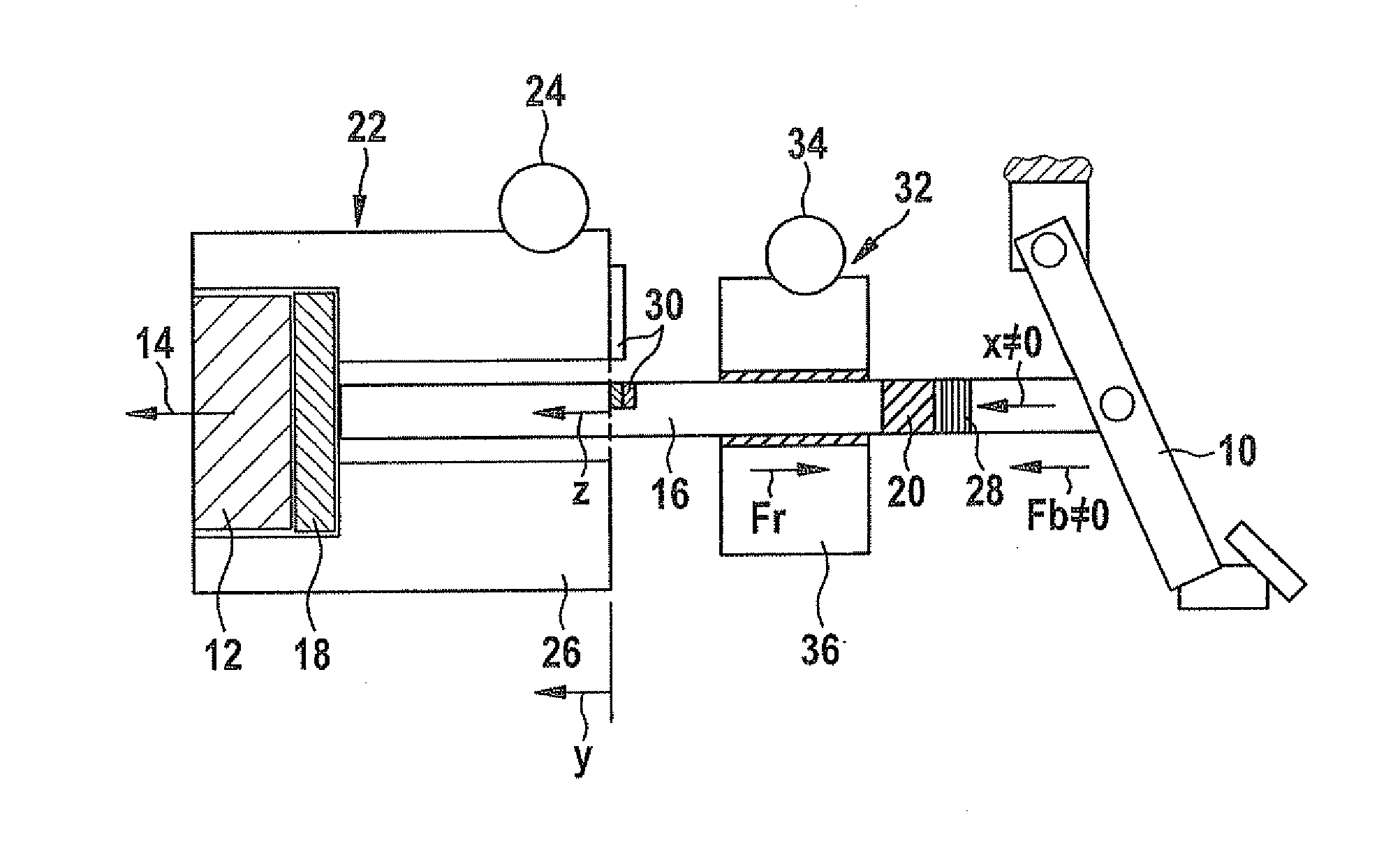
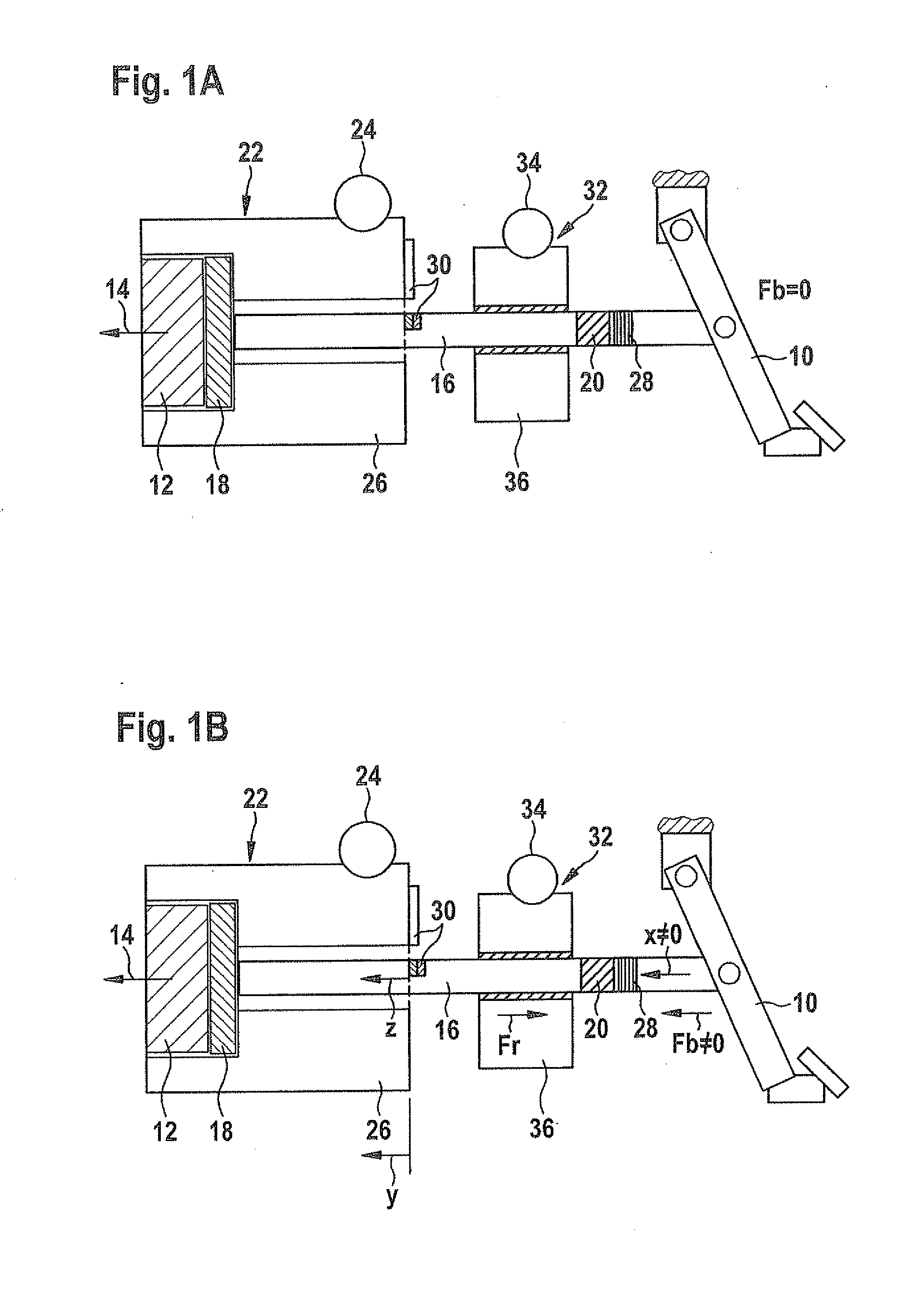
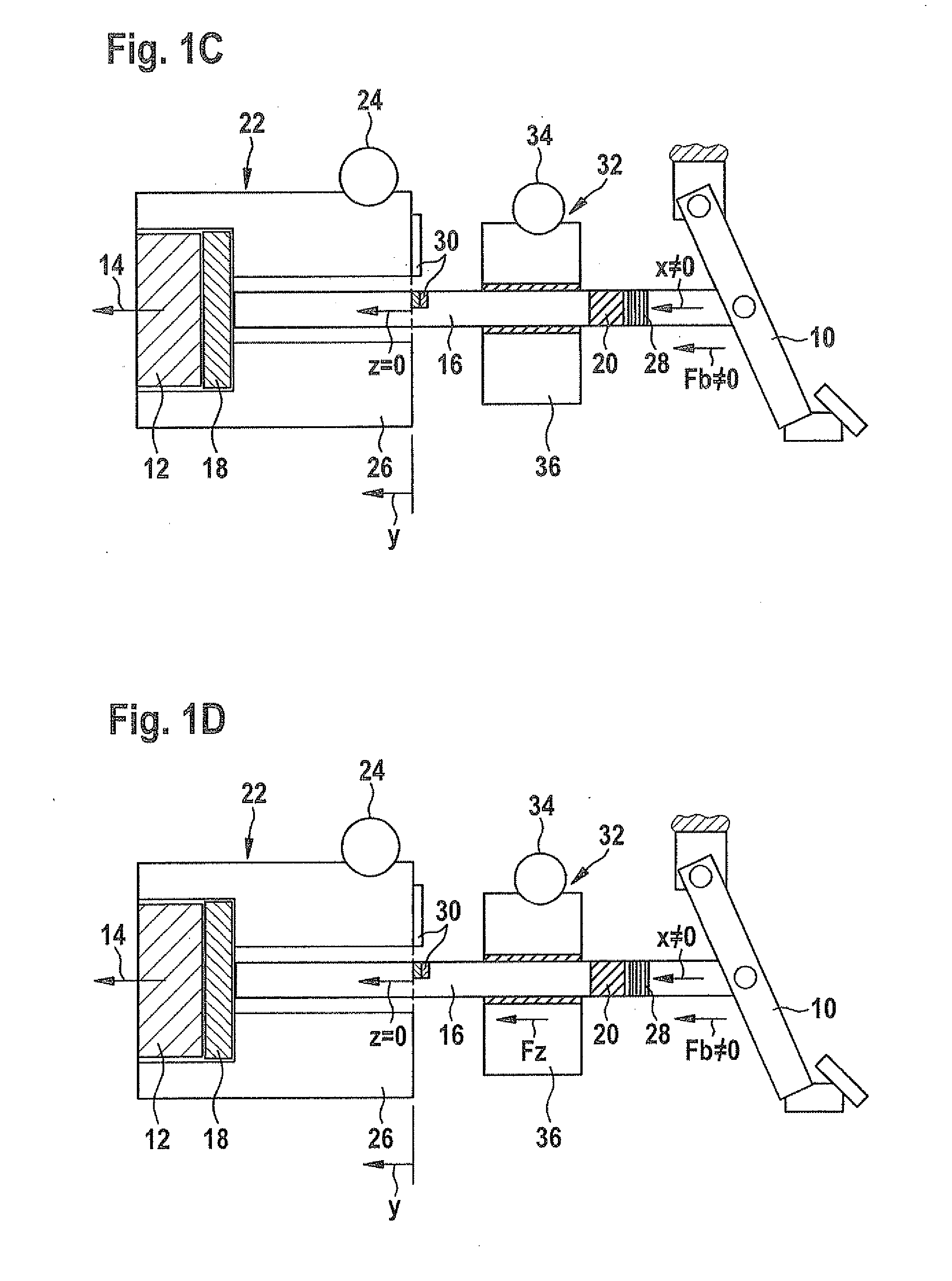
[0016]FIGS. 1A through 1D show schematic illustrations of a first example embodiment of the brake system in various operating modes.

[0017]The brake system, illustrated only partially in FIGS. 1A through 1D, has a brake activation element 10 which is designed as a brake pedal. However, the brake system described here is not limited to a design of brake activation element 10 as a brake pedal. As an alternative or in addition to a brake pedal, the brake system may have, for example, a brake activation element 10 which is designed for manual operation.

[0018]For decelerating a vehicle equipped in this way, the brake system includes a hydraulic braking device (not illustrated) having at least one piston-cylinder unit. An output piston 12 is situated on the piston-cylinder unit in such a way that an internal pressure in the piston-cylinder unit is increasable by displacing output piston 12 in displacement direction 14. For example, for this purpose output piston 12 may be displaceable at l...


PUM


Abstract

A brake system for a vehicle includes: a brake activation element; an input piston displaceable by at least a predefined minimum actuator travel distance when the brake activation element is operated; an output piston to which a driver braking force is transmittable from the brake activation element via the displaced input piston such that an internal pressure in a piston-cylinder unit of the brake system is increased; a first brake booster; and a spring device which, when the brake activation element is operated for an actuator travel distance which is less than the minimum actuator travel distance, is deformed in such a way that transmission of the driver braking force to the output piston is prevented.

Description

BACKGROUND OF THE INVENTION[0001]1. Field of the Invention[0002]The present invention relates to a brake system for a vehicle and a method for operating a brake system for a vehicle.[0003]2. Description of the Related Art[0004]Electric vehicles and hybrid vehicles have a brake system which is designed for regenerative braking, having an electric motor which is operated as a generator during the regenerative braking. The electrical energy obtained during the regenerative braking, after being temporarily stored, is preferably used for accelerating the vehicle. Power loss which a conventional vehicle experiences due to frequent braking during traveling, energy consumption, and exhaust gas emissions of the electric or hybrid vehicle may be reduced in this way.[0005]However, operating the electric motor, the electric drive motor, for example, as a generator generally requires a certain minimum speed of the vehicle. Thus, a regenerative brake system is often not able to exert a generator ...

Claims


Application Information

Patent Timeline
Patent Type & Authority Applications(United States)
IPC IPC(8): B60T13/66B60T8/17B60T7/00
CPCB60T7/042B60T13/745B60T13/588B60T11/18B60T13/586
Inventor WEIBERLE, REINHARDJAHNZ, TIMO
Owner ROBERT BOSCH GMBH
Why Eureka
Try Eureka