Power conditioner for feeding system

a technology of power conditioner and feeding system, which is applied in the direction of cell components, cell component details, greenhouse gas reduction, etc., can solve the problems of not reaching the desired feeder voltage at the terminal end of the feeder, phenomenon (problem), etc., to prevent voltage fluctuation, prevent voltage drop, and mitigate the influence of the power receiving sid

Inactive Publication Date: 2012-04-19
KAWASAKI HEAVY IND LTD
View PDF3 Cites 17 Cited by
  • Summary
  • Abstract
  • Description
  • Claims
  • Application Information

AI Technical Summary

Benefits of technology

[0023]By utilizing the present invention, the power conditioner of the present invention can accommodate active power between feeding circuits and regulate reactive power to prevent a voltage fluctuation at a feeder. Further, the power conditioner of the present invention does not require a capacitor for maintaining a voltage at the feeder.
[0024]The power conditioner of the present invention allows regenerative electric power unconsumed within a certain feeding section to be stored in the nickel-metal hydride battery for reuse. The power conditioner of the present invention allows electric power to be supplied to a feeder by discharging the nickel-metal hydride battery, thereby preventing a voltage drop at a feeder. This makes it possible to mitigate an influence on a power receiving side which would be caused by a rapid fluctuation in an electric train load. Furthermore, by utilizing the power conditioner of the present invention, an electric train stopping in a middle of a certain feeding section can be moved to a nearest station by driving power fed from the nickel-metal hydride battery even when feeding from electric power system is stopped.

Problems solved by technology

In AC feeding, in a single-phase circuit extending from an AC traction substation to a sectioning post, a phenomenon (problem) occurs.
That is, a voltage drop occurs by running of an electric train, due to resistance or reactance of railway impedance in a feeder, and thereby a desired feeder voltage at a terminal end of the feeder is not attained.

Method used


Image

  • Power conditioner for feeding system
  • Power conditioner for feeding system
  • Power conditioner for feeding system

Examples


embodiment 1

1.2. Modified Example of Embodiment 1

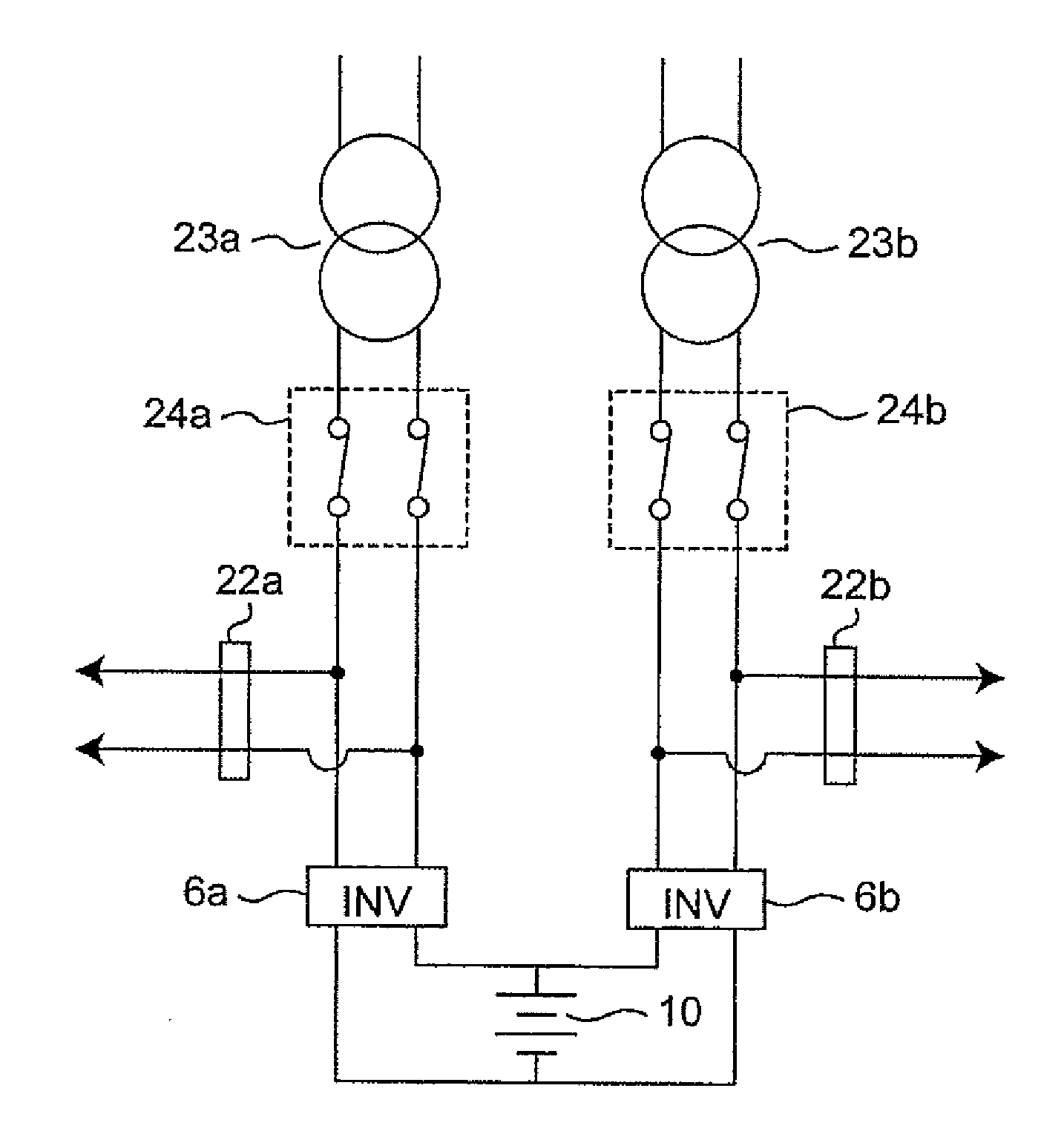
[0075]The power conditioner of FIG. 1 is the SVC installed at the feeding side in the Scott-T transformer which receives three-phase AC power. The power conditioner of Embodiment 1 can be installed in a transformer which receives single-phase AC power. FIG. 6A is a connection diagram of the power conditioner according to Embodiment 1 of the present invention, which is installed at a feeding side in an AC feeding circuit connected to two transformers 23a and 23b which receive single-phase AC power. FIG. 6B is a connection diagram of a comparative example of the AC feeding circuit connected to the two transformers 23a and 23b which receive single-phase AC power.

[0076]In the power conditioner of FIG. 6A, feeders are provided with breakers 22a and 22b which can interrupt power from the transformers 23a and 23b, respectively. A switch 24a is provided between the transformer 23a and the inverter 6a, while a switch 24b is provided between the transforme...

embodiment 2

2. Embodiment 2

[0078]FIG. 7 is a connection diagram of a power conditioner 202 according to Embodiment 2 of the present invention. The power conditioner 202 according to Embodiment 2 constitutes a three-phase SVC installed at receiving side (three-phase side) in the Scott-T transformer 3 in an AC traction substation. R-phase, S-phase, and T-phase indicate inputs at three-phase side in the Scott-T transformer 3, respectively. Main-phase and Teaser indicate two single-phase powers formed at the feeding side in the Scott-T transformer 3, respectively. The SVC 202 of Embodiment 2 includes an inverter 6 connected at its AC side to three-phase inputs, respectively, and the nickel-metal hydride battery 10 connected to DC side in the inverter 6.

[0079]The inverter 6 is similar to the inverter according to the above conventional art. The nickel-metal hydride battery 10 is disposed between and connected to a DC input / output end of the inverter 6 which is connected to a high-voltage cable at th...

embodiment 3

3. Embodiment 3

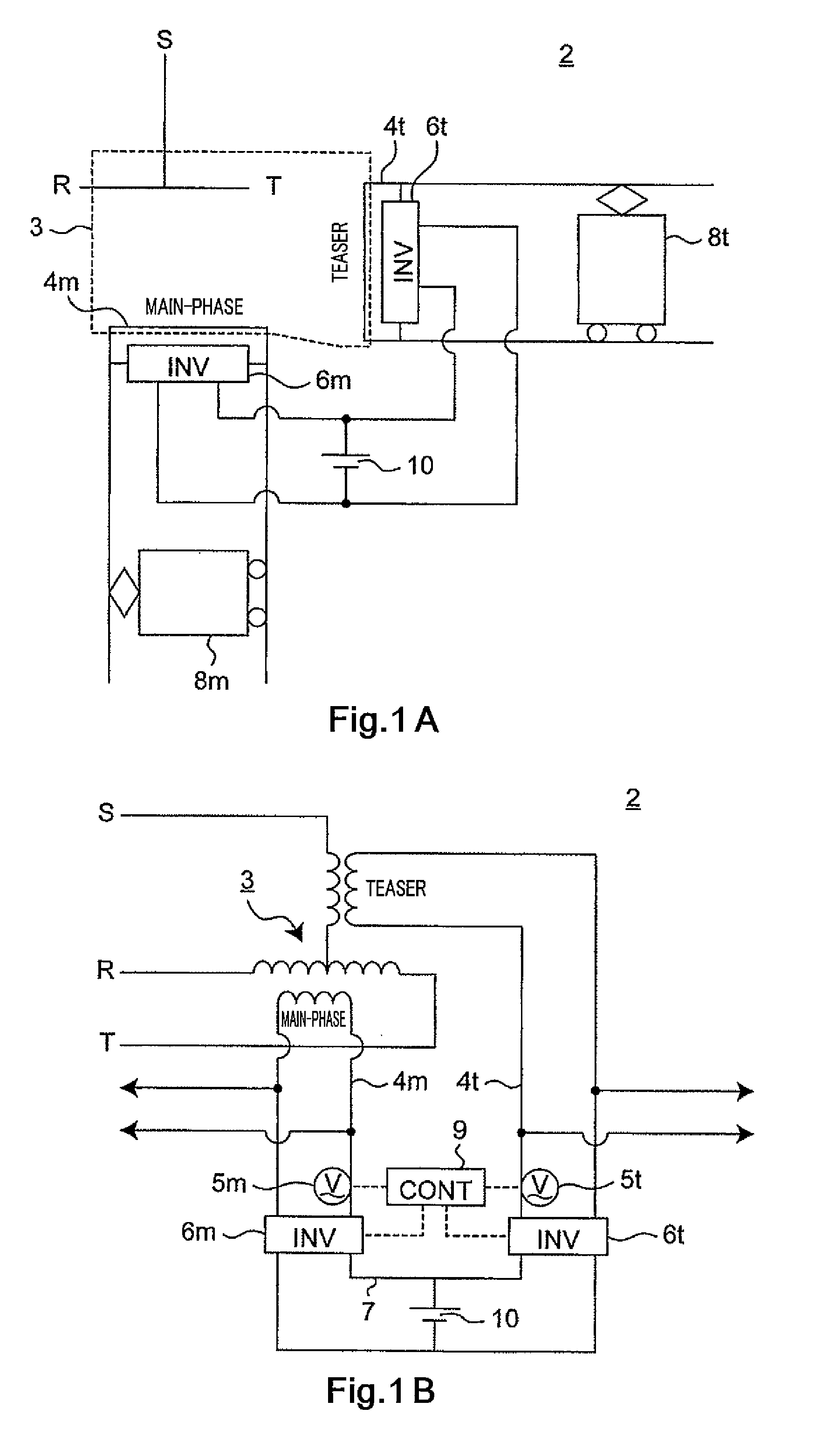
[0082]FIG. 8 is a connection diagram of a power conditioner 402 according to Embodiment 3 of the present invention. The power conditioner 402 according to Embodiment 3 constitutes a single-phase feeding power conditioner (SFC). The single-phase feeding power conditioner (SFC) is configured such that inverters 6m and 6t are installed at Main-phase and Teaser in a scalene Scott-T transformer which performs single-phase feeding by a Slant-phase formed by directly connecting the Main-phase and the Teaser in the Scott-T transformer 3, and these two inverters 6m and 6t are connected to each other.

[0083]In FIG. 8, R-phase, S-phase, and T-phase indicate inputs at three-phase side in the Scott-T transformer, 3 respectively. Main-phase and Teaser indicate two phases formed by the Scott-T transformer 3, respectively. The power conditioner 402 according to Embodiment 3 includes the inverters 6m and 6t connected to the Main-phase and the Teaser, respectively, and the nickel-metal ...


PUM

PropertyMeasurementUnit
receiving voltageaaaaaaaaaa
voltageaaaaaaaaaa

Abstract

A power conditioner for a feeding system which stabilizes a load of active power is provided. A power conditioner for a feeding system comprises a first AC-DC and DC-AC converter for performing conversion between AC power and DC power; and a nickel-metal hydride battery disposed between and connected to a high-voltage cable at DC side of the first AC-DC and DC-AC converter and a low-voltage cable at the DC side of the first AC-DC and DC-AC converter.

Description

TECHNICAL FIELD[0001]The present invention relates to power conditioners for feeding systems for use with electric railways.BACKGROUND ART[0002]An AC feeding circuit is suitable for long-distance and large-capacity power supply, and therefore is used for power supply for bullet trains and others. An electric railway is a single-phase load. Therefore, generally, in AC traction substation, a three-phase to two-phase transformer transforms three-phase power received from electric power companies, etc., into one pair of single-phase powers having a phase difference of 90 degrees (e.g., see Non-Patent Literature 1). As the three-phase to two-phase transformer, a Scott-T transformer (receiving voltage: 66 kV˜154 kV) or a modified Woodbridge transformer (receiving voltage: 187 kV˜275 kV) is used to avoid unbalance of three-phase power supply.[0003]In addition, in order to address a voltage fluctuation, the AC traction substation is equipped with a static VAR compensator (SVC). The SVC not ...

Claims


Application Information

Patent Timeline
Patent Type & Authority Applications(United States)
IPC IPC(8): H02J1/00H02M7/00H01M50/209
CPCB60M3/02Y02E60/721H01M10/345H01M10/5032H01M10/5059H01M10/5063H02J3/32Y02E60/124Y02E70/30B60L2210/30B60L2210/40B60L2200/26Y02T10/7241Y04S10/126H01M2/1061H01M10/647H01M10/6557H01M10/6561Y02E60/10Y02T10/72H01M50/209Y02E60/00
Inventor TSUTSUMI, KAZUOMATSUMURA, TAKAHIROTONDA, CHIYOHARU
Owner KAWASAKI HEAVY IND LTD
Why Eureka
Try Eureka