Thermoelectric conversion module and thermoelectric conversion element

a technology of thermoelectric conversion module and conversion element, which is applied in the direction of thermoelectric device junction materials, electrical apparatus, and thermoelectric device with peltier/seeback effect, etc., can solve the problems of breaking the jointing layer made of the jointing material, and achieve the effect of suppressing thermal stress

Inactive Publication Date: 2012-04-26
SUMITOMO CHEM CO LTD
View PDF15 Cites 29 Cited by
  • Summary
  • Abstract
  • Description
  • Claims
  • Application Information

AI Technical Summary

Benefits of technology

[0003]However, the thermoelectric conversion module above produces large thermal stress between the thermoelectric conversion element and the electrode during electric power generation, and therefore joining layers made of the jointing material get broken when thermal cycles have been carried out repeatedly. It is an object of the invention to provide a thermoelectric conversion module that can suppress thermal stress produced between the thermoelectric conversion element and electrode, and a thermoelectric conversion element favorable for the module.

Problems solved by technology

However, the thermoelectric conversion module above produces large thermal stress between the thermoelectric conversion element and the electrode during electric power generation, and therefore joining layers made of the jointing material get broken when thermal cycles have been carried out repeatedly.

Method used


Image

  • Thermoelectric conversion module and thermoelectric conversion element
  • Thermoelectric conversion module and thermoelectric conversion element
  • Thermoelectric conversion module and thermoelectric conversion element

Examples


example 1

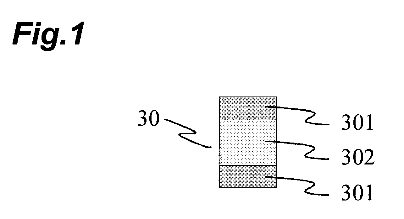
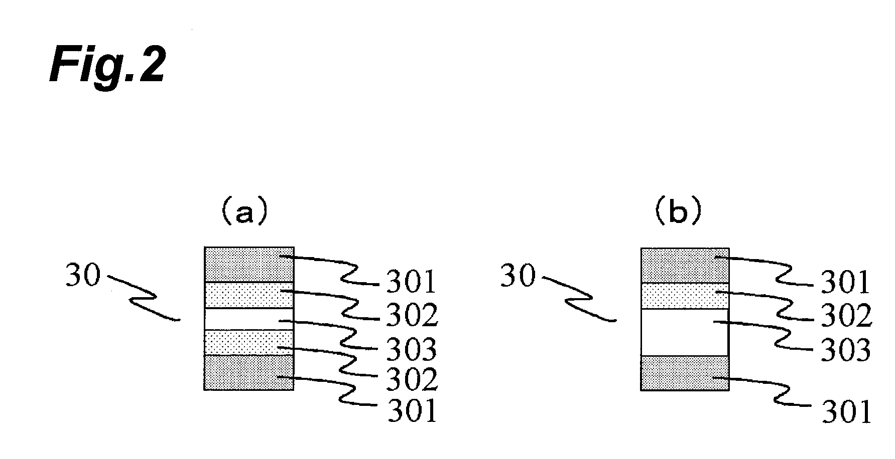
First Layer: 70% by Mole Thermoelectric Conversion Material (CaMn0.98Mo0.02O3+CuO)+30% by Mole Conductive Metal (Ag); Second Layer: 100% by Mole Thermoelectric Conversion Material (CaMn0.98Mo0.02O3+CuO)

[0068]After weighing out:

8.577 g of CaCO3 (trade name: CS3N-A, by Ube Material Industries, Ltd.),

7.852 g of MnO2 (product of Kojundo Chemical Lab. Co., Ltd.),

0.247 g of MoO3 (product of Kojundo Chemical Lab. Co., Ltd.),

0.359 g of CuO (product of Kojundo Chemical Lab. Co., Ltd.), and

4.482 g of Ag2O (product of Kojundo Chemical Lab. Co., Ltd.),

they were mixed for 20 hours with a wet ball mill (medium: zirconia ball) and held in air at 900° C. for 10 hours to be calcined, obtaining a calcined product thereby. The calcined product was pulverized for 20 hours with a wet ball mill (medium: zirconia ball) to obtain powder 1 (powder for formation of the first layer). Powder 1 had the same type of crystal structure as perovskite-type crystals of CaMnO3. An Ag crystal structure peak was detecte...

example 2

First Layer: 80% by Mole Thermoelectric Conversion Material (CaMn0.98Mo0.02O3+CuO)+20% by Mole Conductive Metal (Ag); Second Layer: 100 Mol % Thermoelectric Conversion Material (CaMn0.98MO0.02O3+CuO)

[0072]Sintered body 3 was fabricated in the same manner as Example 1, except that the amount of Ag2O for production of powder 1 was changed to 2.614 g. Sintered body 3 had a contact resistance of 25, which was low relative to sintered body 1. Because of the low contact resistance, sintered body 3 is suitable as a thermoelectric conversion element in a thermoelectric conversion module in which the thermoelectric conversion elements and electrodes are electrically connected without joints.

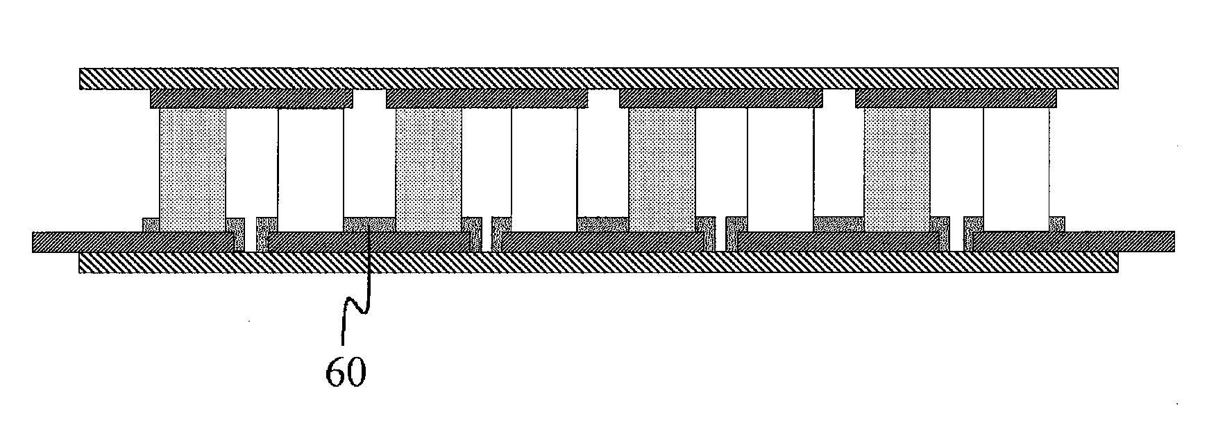
[0073]Ag plates (2 plates in total) were, without a joint, attached to both ends of sintered body 3 and the element-electrode link was formed by applying a pressure of 2 kg / cm2. The element-electrode resistance in the link was 0.2Ω. A thermal cycle of the link was performed repeatedly in the same manner a...


PUM

PropertyMeasurementUnit
temperaturesaaaaaaaaaa
molar ratioaaaaaaaaaa
conductiveaaaaaaaaaa

Abstract

The invention provides a thermoelectric conversion module and a thermoelectric conversion element. The thermoelectric conversion module comprises a plurality of thermoelectric conversion elements and a plurality of electrodes, wherein each of the thermoelectric conversion elements is made of a sintered body containing a thermoelectric conversion material and a conductive metal, has two faces, and satisfies the following condition (a) or (b): (a) each thermoelectric conversion element is electrically connected to an electrode via one face without a joint and is electrically connected to another electrode via the other face with a joint, (b) each thermoelectric conversion element is electrically connected to an electrode via one face without a joint and is electrically connected to another electrode via the other face without a joint.

Description

TECHNICAL FIELD[0001]The present invention relates to a thermoelectric conversion module and to a thermoelectric conversion element.BACKGROUND ART[0002]Thermoelectric conversion power generation is a type of electric power generation by method in which thermal energy is converted to electrical energy. In thermoelectric conversion power generation, electricity is generated by thermoelectromotive force produced by applying a temperature difference in the thermoelectric conversion element of the thermoelectric conversion module. Since heat generated geothermally or waste heat from an incinerator can be used as thermal energy, thermoelectric conversion power generation is expected as an environmentally friendly form of electric power generation. A thermoelectric conversion module normally has p-type thermoelectric conversion elements and n-type thermoelectric conversion elements electrically connected in series via electrodes, with the thermoelectric conversion elements being joined to ...

Claims


Application Information

Patent Timeline
Patent Type & Authority Applications(United States)
IPC IPC(8): H01L35/04
CPCH01L35/22H01L35/06H10N10/813H10N10/855
Inventor SADAOKA, KAZUOSAWABE, YOSHINARIHIROYAMA, YUICHI
Owner SUMITOMO CHEM CO LTD
Why Eureka
Try Eureka