Film formation apparatus and film forming method

a film forming apparatus and film forming technology, applied in the direction of vacuum evaporation coating, electrolysis components, coatings, etc., can solve the problems of asymmetric coverage formation, asymmetric coating formation, and different shape of the film formed between the bottom of the microscopic hole and one of the side walls thereof, so as to achieve the same film formation effect and high level of coatability

Inactive Publication Date: 2012-04-26
ULVAC INC
View PDF9 Cites 33 Cited by
  • Summary
  • Abstract
  • Description
  • Claims
  • Application Information

AI Technical Summary

Benefits of technology

[0021]According to the invention, since a perpendicular magnetic field is generated so that the perpendicular magnetic field lines pass between the entire surface of the target and the entire surface of the body to be processed, the directions of the sputtered particles which have positive electrical charge and are scattered from the sputtering face of the target by sputtering are changed due to the above-described perpendicular magnetic field.
[0022]Because of this, the sputtered particles are substantially perpendicularly directed to the body to be processed and adhered thereto.
[0023]As a result, it is possible to form a coat with a high level of coatability in the holes, the trenches, or the microscopic patterns, which have a high-aspect ratio, by use of the film formation apparatus o

Problems solved by technology

As a result, in the case where the sputtering apparatus is used for the aforementioned film formation step, particularly, it is conventionally known that a problem of asymmetric coverage being formed at the peripheral portion of the substrate.
Particularly, in the cross-sectional face of the microscopic holes formed at the peripheral portion of the substrate, there is a problem in that the shape of a coat formed between the bottom of the microscopic holes and one of the side walls thereof is different from the shape of a coat formed between the bottom of the microscopic holes and

Method used


Image

  • Film formation apparatus and film forming method
  • Film formation apparatus and film forming method
  • Film formation apparatus and film forming method

Examples


examples

[0112]Next, Examples of a film formation apparatus and a film forming method of the invention will be described.

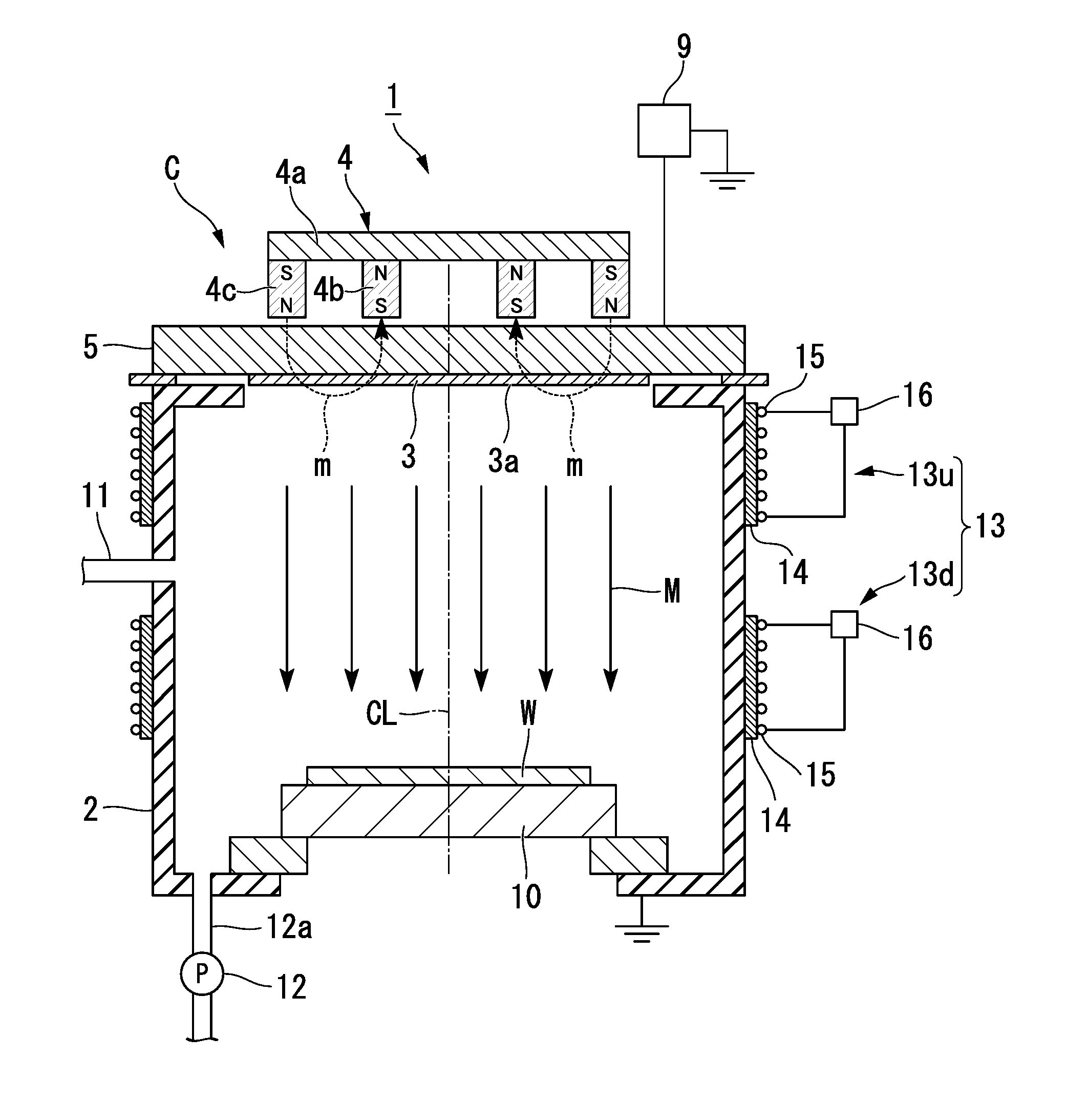
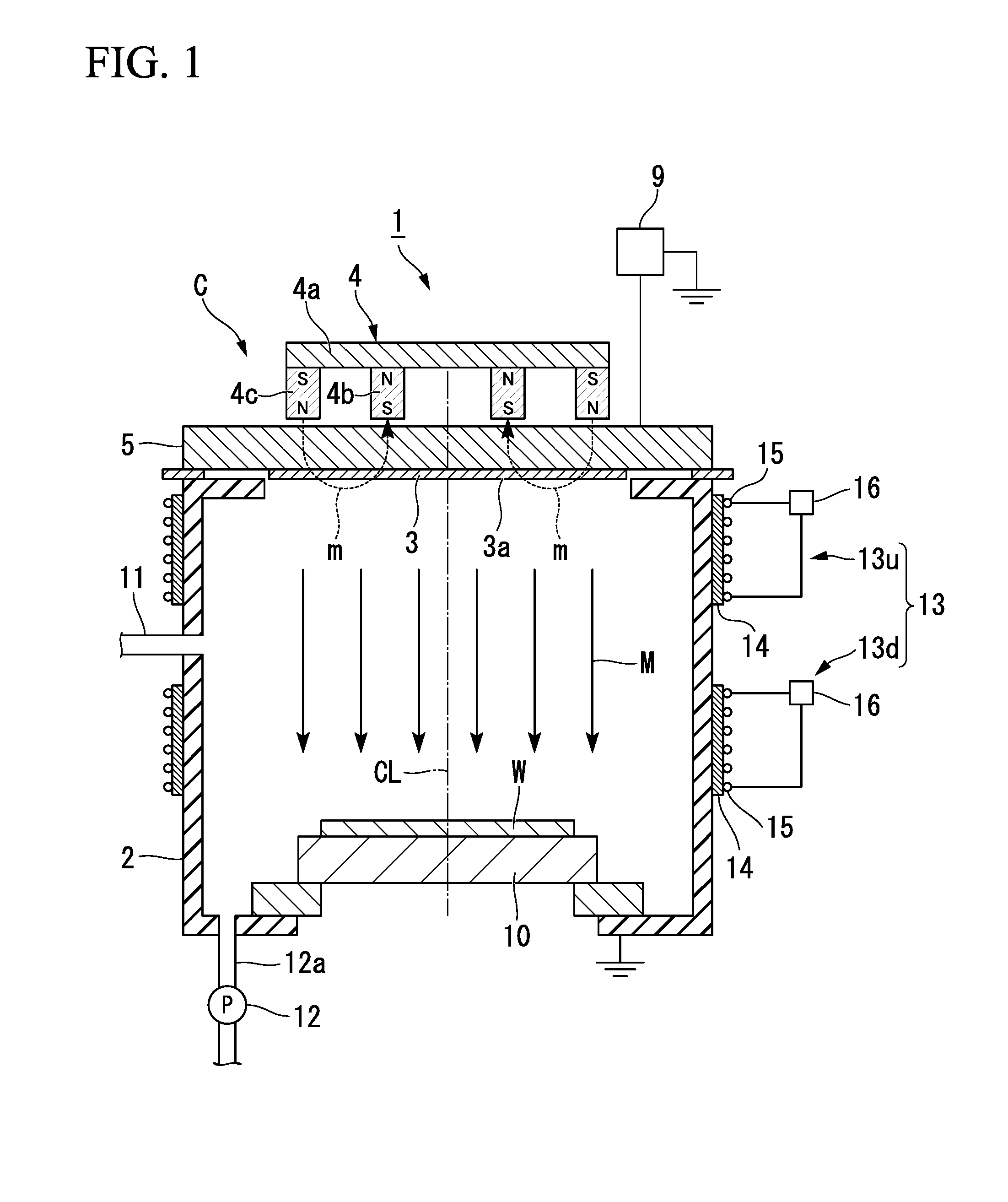
[0113]In this Example, a Cu coat was formed on the substrate W by use of the film formation apparatus 1 shown in FIG. 1.

[0114]Specifically, the substrate W was prepared such that a silicon oxide film was formed over the entirety of the top face of a Si wafer of φ300 mm and microscopic trenches (the width thereof is 40 nm and the depth thereof is 140 nm) was formed on this silicon oxide film by patterning using a known method.

[0115]In addition, as a target, the target was used which is manufactured so that the compositional ratio of Cu is 99% and the diameter of the sputtering face is φ400 mm

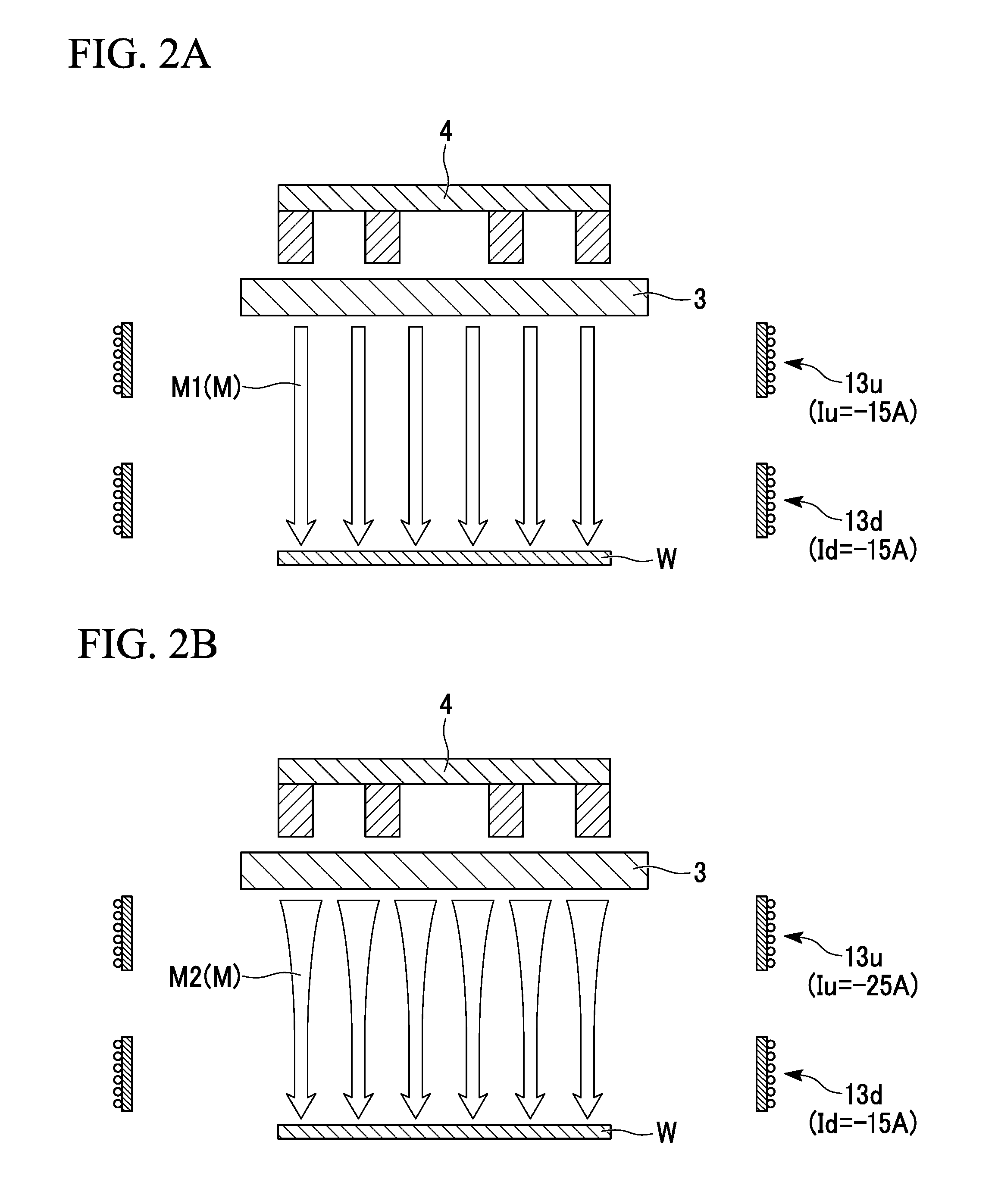
[0116]The distance between the target and the substrate was determined to be 400 mm, and the distance between the lower edge of the upper coil 13u and the target 3 and the distance between the upper edge of the lower coil 13d and the substrate W were determined to be 50 mm, respectively...


PUM


Abstract

A film formation apparatus includes: a chamber in which both a body to be processed and a target are disposed; a first magnetic field generation section generating a magnetic field; and a second magnetic field generation section including a first generation portion to which a current defined as “Iu” is applied and a second generation portion to which a current defined as “Id” is applied, the first generation portion being disposed at a position close to the target, the second generation portion being disposed at a position close to the body to be processed, the second magnetic field generation section applying the currents to the first generation portion and the second generation portion so as to satisfy the relational expression Id<Iu, the second magnetic field generation section allowing perpendicular magnetic lines to pass between the target and the body to be processed.

Description

BACKGROUND OF THE INVENTION[0001]1. Field of the Invention[0002]The present invention relates to a film formation apparatus and a film forming method which are used for forming a coat on a surface of a body to be processed, and particularly, relates to a film formation apparatus and a film forming method employing a DC magnetron method using a sputtering method which is one of several thin film forming methods.[0003]This application claims priority from Japanese Patent Application No. 2009-169447 filed on Jul. 17, 2009, the contents of which are incorporated herein by reference in their entirety.[0004]2. Background Art[0005]Conventionally, a film formation apparatus using a sputtering method (hereinafter, refer to “sputtering apparatus”) is used in a film formation step in which, for example, a semiconductor device is manufactured.[0006]As a sputtering apparatus of such intended use, with miniaturizing of wiring pattern in recent years, an apparatus is increasingly and strongly requ...

Claims


Application Information

Patent Timeline
IPC IPC(8): C23C14/35
CPCC23C14/046C23C14/165H01L21/76843H01L21/2855C23C14/351C23C14/54
Inventor KODAIRA, SHUJIYOSHIHAMA, TOMOYUKIKAMADA, KOUKICHIHORITA, KAZUMASAHAMAGUCHI, JUNICHINAKANISHI, SHIGEOTOYODA, SATORU
Owner ULVAC INC
Why Eureka
Try Eureka