
Wastewater treatment system

Inactive Publication Date: 2012-04-26
EARLY DANIEL M +1
View PDF2 Cites 27 Cited by
  • Summary
  • Abstract
  • Description
  • Claims
  • Application Information

AI Technical Summary

Benefits of technology

[0023]A second port is formed through the first partition wall for selective transfer of the wastewater from the second chamber to the third chamber. The third chamber includes a return activated sludge pump assembly and at least one second effluent filter. A third port is formed through the second partition wall for selective transfer of settled waste solids from the third chamber to the first chamber. Resultant purified water is selectively discharged from the outlet port, after passing through the second effluent filter. Preferably, the tank is equipped with a bottom plate, which serves as an antifloatation collar, thereby preventing inadvertent floatation of an empty tank that may occur during or after construction.

Problems solved by technology

The discharge of untreated wastewater is not suitable, since it gives rise to numerous environmental concerns, such as the pollution of surface and groundwater resources.
Untreated wastewater contains organic matter and nutrients that, if left untreated and not removed from the waste stream, can result in environmental pollution.
Thus, when untreated wastewater is released into either aboveground bodies of water or subsurface drainfields, the level of dissolved oxygen in the receiving waters begins to deplete, which endangers the water bodies themselves, along with the resident plant and aquatic life.
However, there are several problems associated with large, centralized treatment plants.
Thus, if a centralized treatment plant receives more wastewater on a particular day than what the plant was designed to handle, problems are encountered.
As noted above, discharge of this untreated wastewater into bodies of water will endanger and kill resident plant and aquatic life in the water.
Untreated wastewater also contains a number of disease pathogens that are extremely harmful to humans.
For example, untreated wastewater is one of the leading causes of dysentery, which can be life threatening.
Thus, if a significant amount of untreated wastewater is discharged into a body of water, that body of water will become unavailable for human consumption.
On the other hand, if the treatment plant processes the larger-than-normal amounts of untreated wastewater, instead of diverting a portion into a body of water, the influx of untreated wastewater would wash away the bacteria populations or biomass used by the plant to treat the untreated wastewater, which would disrupt the entire biological treatment process of the plant.
Further, as noted above, wastewater treatment is particularly needed in developing nations, and such large-scale treatment plants may not be available.
In rural areas and in developing nations, construction of centralized wastewater treatment plants may be too expensive to build and maintain.
In addition, the cost of connecting residences and businesses in rural areas to a centralized treatment plant via sewage lines may be impracticable due to the greater distance between the those residences and businesses.
However, since the wastewater leaving the septic tank has only been minimally treated, the wastewater will be a detriment to the environment due to its organic and nutrient contaminants, as noted above, and may not be recovered as reclaimed water.
Furthermore, as solids build up inside the septic tank, a phenomenon known as periodic upset may occur, causing solids to flow out of the septic tank and into the field lines connected to the tank.
Eventually, these field lines will clog due to the buildup and carryover of solids.
When this occurs, the field lines have to be cleaned or replaced, if possible, which means destruction to a portion of the owner's property as well as increased expense to the owner.
A more extreme condition would be the failure of the drain field without an adequate replacement area on the property.
Further, it has been found that certain soils are only capable of receiving and dispersing a limited amount of wastewater, given the particular soil structure, geology, and groundwater conditions.
These materials have been utilized for decades, due to the unavailability of other options.
Concrete and steel, due to their particular material properties, are highly subject to corrosion and are not suited to withstand the corrosive gases and fluctuations in pH common in wastewater and wastewater treatment.
Further, both concrete and steel tanks are difficult and expensive to fabricate, transport and install.
Fiberglass, although a more tolerant material with a longer life expectancy, is limited in its detailing capabilities and delaminates when subjected to a sharp pressure point or conditions of constant friction.
Fiberglass tanks are typically constructed utilizing pre-developed molds and are relatively inflexible in adjustment to specific project requirements.
This inflexibility results in additional required tankage, yard piping and mechanical equipment, thus resulting in increased maintenance and operational issues and expenses.
Additionally, steel, concrete and fiberglass tanks are all relatively difficult to repair when damaged.
However, the overall majority of these tanks are prone to crushing when emptied and are limited in size due to the pre-developed molds.
Molded plastic is used on a limited basis and in small volumes due to structural inadequacies in buried applications.
Steel and concrete systems have limited life expectancies due to the material makeup previously noted.
Fiberglass tanks are limited in their volumes due to pre-developed molds and are much more expensive on a first-cost basis.
Tanks formed from conventional materials are relatively heavy, thus making transportation difficult and expensive.
Further, present mobile water storage tanks are subject to structural damage and severe temperatures.
This current standard is time intensive and typically involves numerous trades and materials.
The construction phase also opens the possibility of vandalism and theft, and the finished product is susceptible to natural disasters, such as hurricanes, tornados, earthquakes and the like.
Furthermore, mobile containerized water treatment systems, while quickly mobilized, watertight and protected, are limited in treatment volumes by the container size.

Method used


Image

  • Wastewater treatment system
  • Wastewater treatment system
  • Wastewater treatment system

Examples


Embodiment Construction

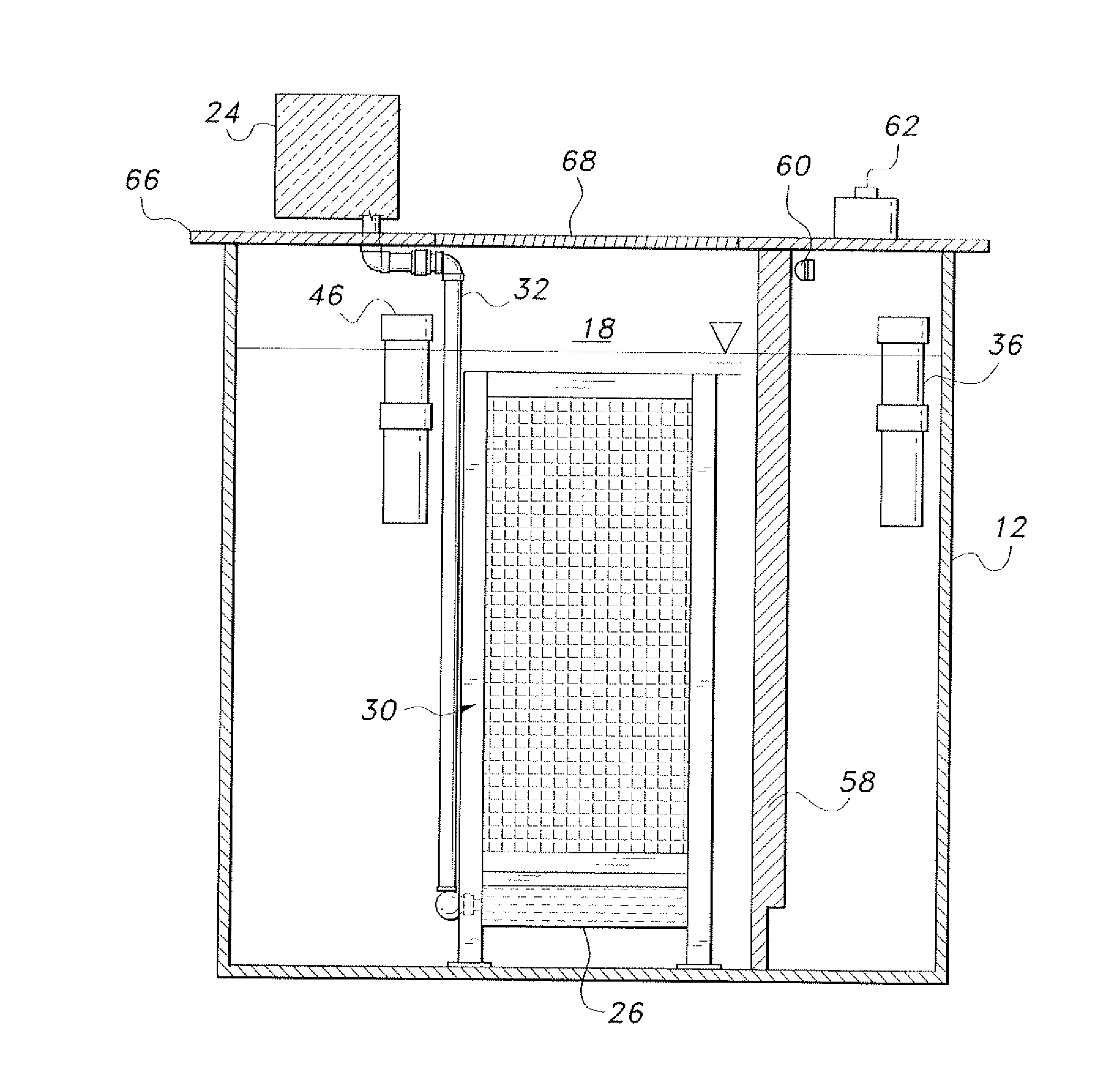
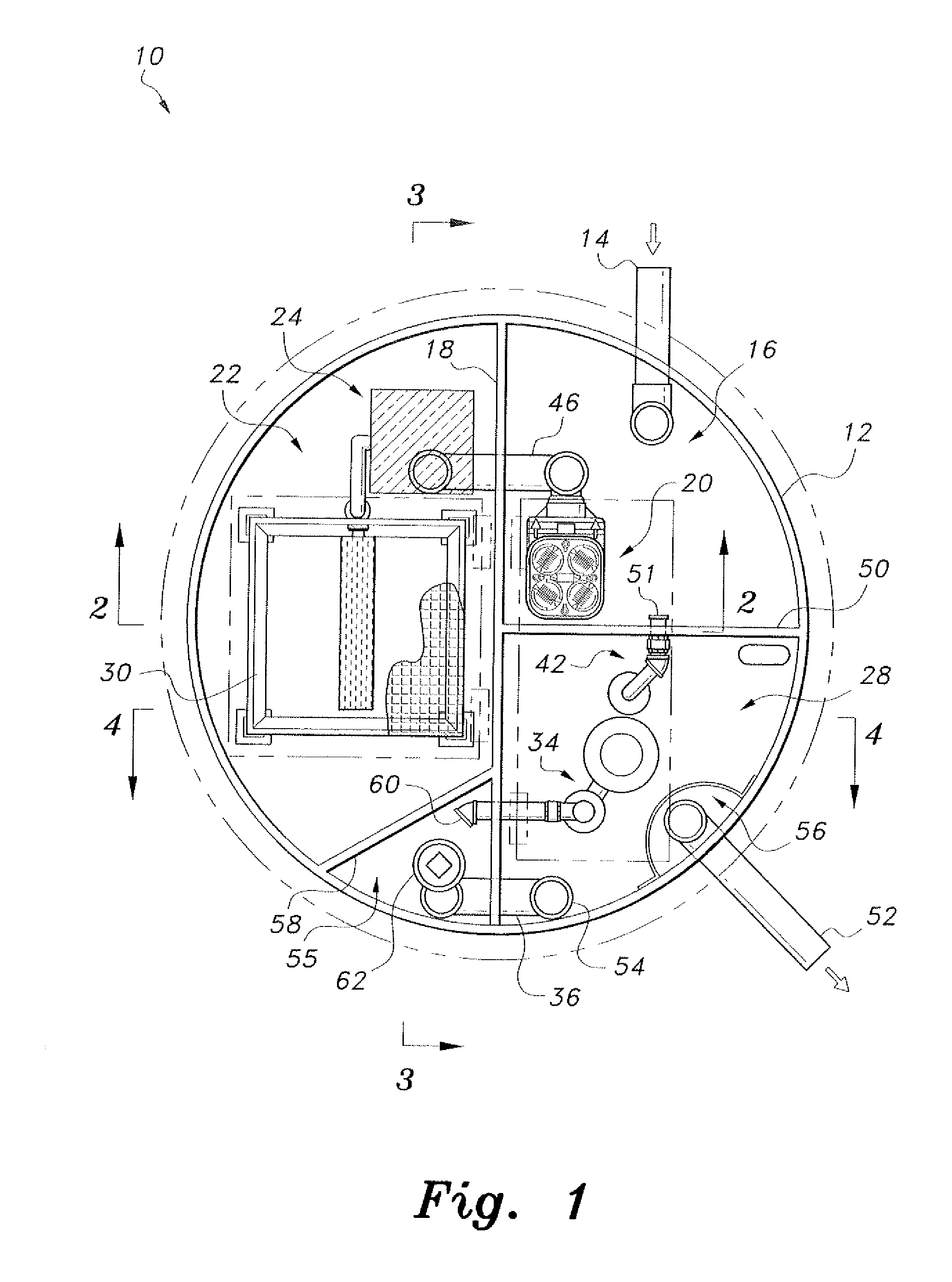
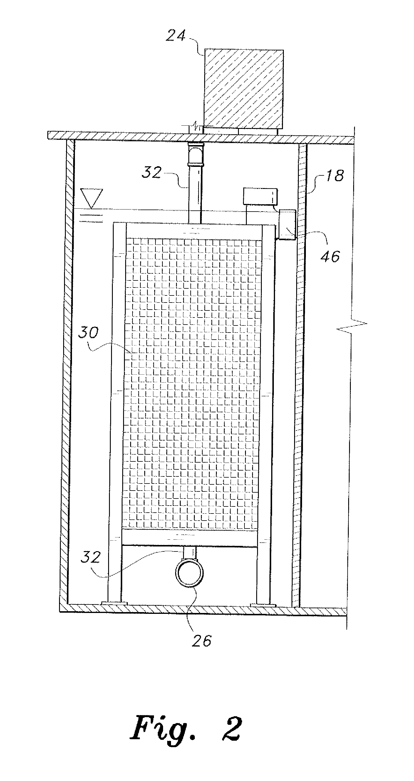
[0068]Referring to FIGS. 1-4, in a first embodiment, the wastewater treatment system 10 is preferably formed as a single enclosed unit contained within a housing 12. The housing 12 is substantially cylindrical, and is preferably formed from steel-reinforced plastic or the like. As will be described in detail below, the system 10 provides three separate techniques for decontaminating wastewater contained within the single system, thus optimizing the decontamination of the wastewater.

[0069]The wastewater treatment system 10 includes the housing 12 forming an outer tank, and first and second partition walls 18, 50, respectively, dividing the tank into first, second and third chambers 16, 22, 28, respectively. The first partition wall 18 generally bisects the cylindrical housing 12 diametrically, and the second partition wall 50 is orthogonal to the first partition wall 18, extending radially and generally bisecting one of the two semicylindrical spaces formed by the first partition wal...


PUM

PropertyMeasurementUnit
Pressureaaaaaaaaaa
Densityaaaaaaaaaa
Electrical conductoraaaaaaaaaa

Abstract

The wastewater treatment system includes a hollow, elongate, horizontally disposed, cylindrical body made from plastic is adapted for water storage and treatment. The cylindrical body includes reinforcement ribs formed by a helically wound steel band embedded in the plastic and extending between opposite open ends of the elongate cylindrical body. A voltage source selectively energizes the steel band. A pair of bulkhead members respectively extends across and covers opposite ends of the cylindrical body. A fluid-tight wall is mounted in the cylindrical body, the first bulkhead member, the fluid-tight wall and the cylindrical body forming a fluid-tight tank defining a liquid storage chamber. The second bulkhead member and the fluid-tight wall define a dry liquid treatment equipment chamber. An inlet pipe extends into the tank for admitting the pretreatment liquid into the tank. An outlet pipe extends from the tank and discharges the treated liquid from the tank.

Description

CROSS-REFERENCE TO RELATED APPLICATION[0001]This application is a continuation-in-part of U.S. patent application Ser. No. 13 / 005,309, filed Jan. 12, 2011, which claims the benefit of U.S. Provisional Patent Application Ser. No. 61 / 282,281, filed Jan. 13, 2010.BACKGROUND OF THE INVENTION[0002]1. Field of the Invention[0003]The present invention relates to water supply treatment systems, and particularly to a wastewater treatment system that removes biodegradable fats, oil, grease, solids, organic contaminants, nutrients, pathogens and the like from wastewater generated in residential homes, commercial businesses, industrial facilities, municipal facilities, agricultural facilities and the like. The present invention further relates to water storage tanks and the like.[0004]2. Description of the Related Art[0005]In order to protect the environment and promote public health, communities typically require wastewater treatment. The discharge of untreated wastewater is not suitable, sinc...

Claims


Application Information

Patent Timeline
IPC IPC(8): C02F1/48F03B11/02
CPCC02F1/485C02F3/06C02F3/1242C02F3/1247C02F1/484C02F2203/008B65D90/10C02F1/001C02F3/105Y02W10/37Y10T137/863Y10T137/8593Y02A20/208Y02W10/10
Inventor EARLY, DANIEL M.EASTER, SCOTT F.
Owner EARLY DANIEL M
Learn More