
Electrical tomography apparatus and method and current driver

Active Publication Date: 2012-04-26
UNIV OF LEEDS
View PDF11 Cites 19 Cited by
  • Summary
  • Abstract
  • Description
  • Claims
  • Application Information

AI Technical Summary

Benefits of technology

[0018]The apparatus in accordance with this first aspect is able to deliver large currents to the electrodes, and consequently large response voltages may be developed on electrodes used for monitoring potentials developed in the medium to be evaluated. Large response voltages on measurement electrodes are beneficial to enhance the signal to noise ratio. Also, the use of the first transformer in the generation of the voltage across the electrodes to drive current through the medium contributes to a high common mode voltage rejection ratio.
[0044]Again, use of the first transformer provides the advantage of isolating common mode voltage from the medium under test (i.e. the medium to be evaluated).

Problems solved by technology

However, problems arise when the medium to be evaluated is a fluid having a relatively high conductivity.
Clearly, output currents from any given current source are limited, and hence measurement of the small voltages developed in or across the medium may be difficult due to the presence of noise.
In other words, a low signal to noise ratio is a problem associated with ERT techniques used to evaluate high conductivity fluids.
The presence of a common mode voltage is a further problem associated with attempts to use ERT techniques for evaluating high conductivity fluids.
A further problem is the handling of large dynamic ranges in voltage signals from measurement electrodes to be digitised (for example by an ADC) so that they can be subsequently processed.

Method used


Image

  • Electrical tomography apparatus and method and current driver
  • Electrical tomography apparatus and method and current driver
  • Electrical tomography apparatus and method and current driver

Examples


Embodiment Construction

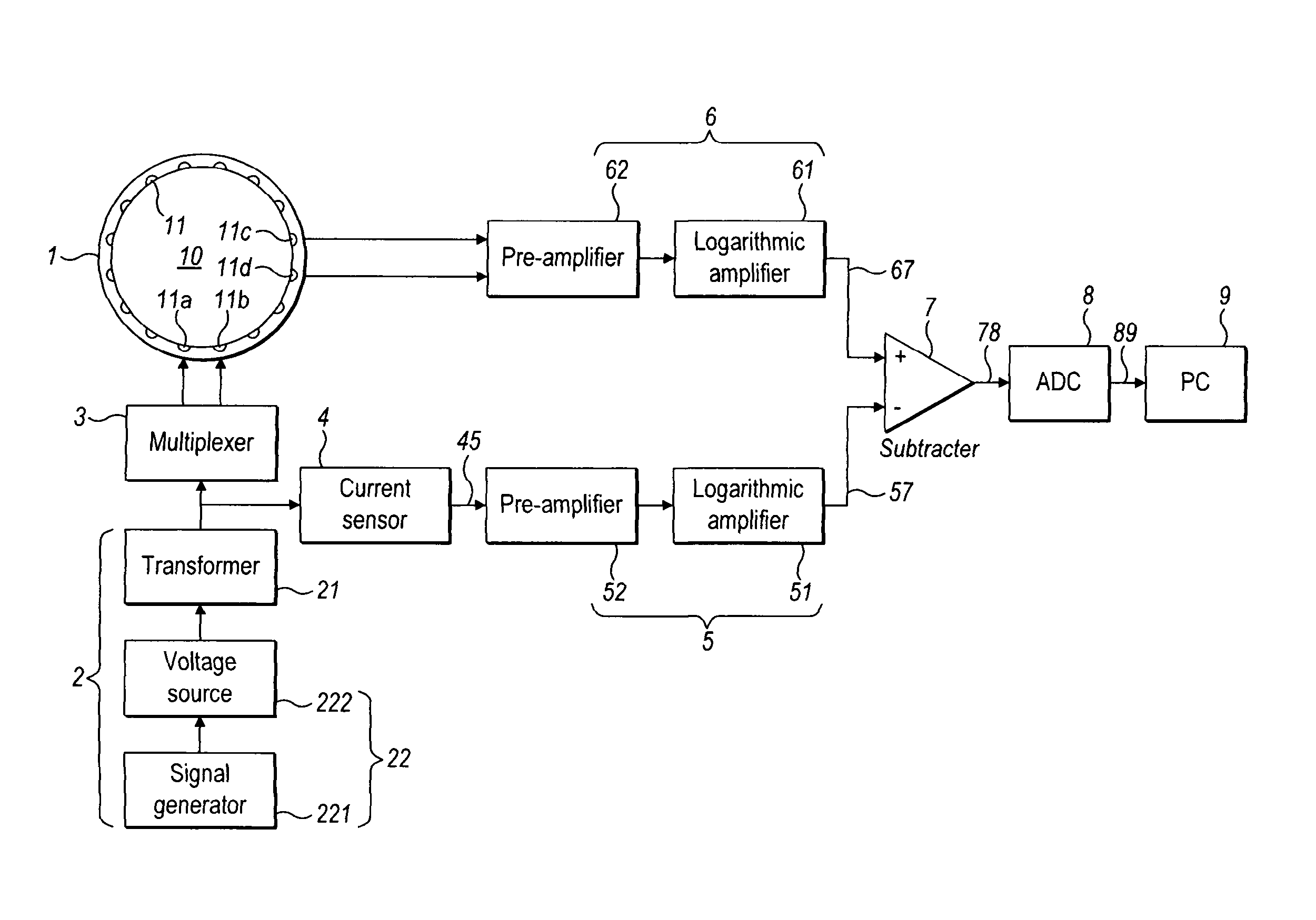
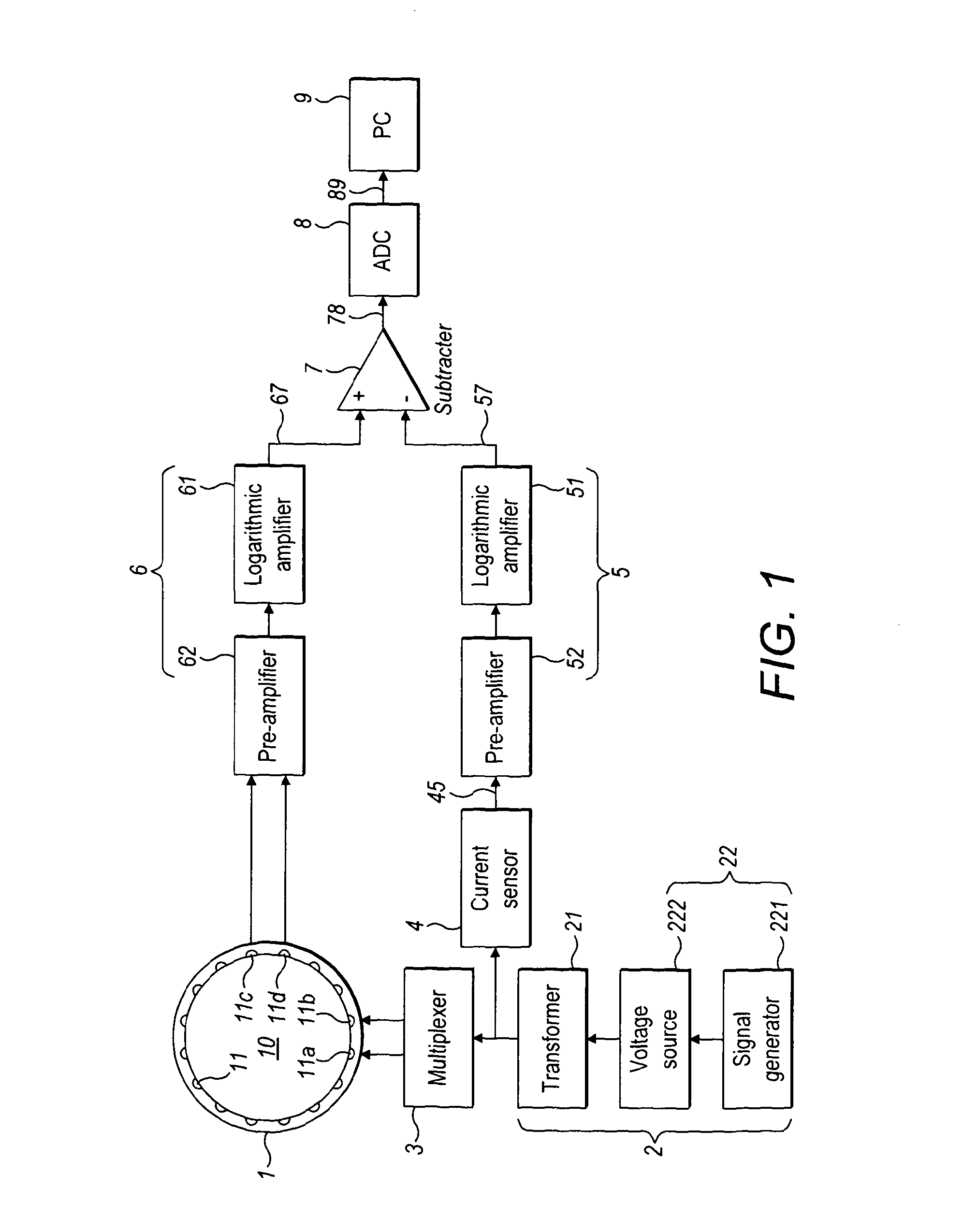
[0077]Referring now to FIG. 1, this shows electrical tomography apparatus embodying the invention. The apparatus comprises containment means 1 having an internal space 10 for containing a medium to be evaluated. A plurality of electrodes 11 are attached to the containment means, and are arranged and spaced apart equally around an inner surface such that each electrode 11 will be in direct contact with a liquid contained in the internal volume 10. These electrodes include a first electrode 11a, a second electrode 11b, a third electrode 11c, and a fourth electrode 11d.

[0078]The apparatus comprises current driving means 2 for driving an electrical current between the first electrode 11a and the second electrode 11b through a medium in contact with the electrodes and inside the containment means 1. The current driving means comprises a first transformer 21 having a first winding 211 and a second winding 212, the second winding having a first terminal 2121 and a second terminal 2122. Th...


PUM


Abstract

Electrical tomography apparatus comprises: a first electrode; a second electrode; and current driving means for driving an electrical current between the first electrode and the second electrode through a medium, wherein the current driving means comprises: a first transformer having a first winding and a second winding, the second winding having a first terminal and a second terminal; and means for generating an alternating current through the first winding so as to generate an alternating voltage between said first terminal and said second terminal. The apparatus further comprises connecting means arranged to connect the first terminal to the first electrode and the second terminal to the second electrode. Generation of the alternating current in the first winding results in generation of an alternating voltage between the first and second electrodes. In certain embodiments, a current sensing transformer provides an indication of current driven through the medium.

Description

FIELD OF THE INVENTION[0001]One aspect of the present invention relates to electrical tomography apparatus and methods, and certain embodiments relate in particular, although not exclusively, to tomography sensing systems for high conductivity fluids. Certain aspects of the present invention are concerned with apparatus and methods for driving electrical current between a pair of electrodes via a medium, and with electrical test apparatus and methods utilising such current driving apparatus and methods.BACKGROUND TO THE INVENTION[0002]Certain embodiments of the invention relate to electrical tomography, and may utilise electrode arrangements (e.g. electrode arrays) known in the art. Certain embodiments may also be used for electrical tomography applications known in the art.[0003]Known electrical tomography techniques include electrical impedance tomography (EIT), electrical resistance tomography (ERT), and electrical capacitance tomography (ECT). EIT is known for use as a medical i...

Claims


Application Information

Patent Timeline
IPC IPC(8): G01R27/28
CPCG01N27/026
Inventor WANG, MIJIA, JIABIN
Owner UNIV OF LEEDS
Learn More