
Multi-core low reflection lateral output fiber probe

a fiber probe and low reflection technology, applied in the direction of cladded optical fibre, instruments, optical elements, etc., can solve the problems of difficult assembly and alignment of such multiple fiber probes, the multi-core nature of single optical fiber, and the limitation of the number of optical probes of this kind that may be distributed within the circumference of the probe housing. achieve the effect of improving the quality of the produ

Inactive Publication Date: 2012-04-26
ALPHONSE GERARD ARGANT +1
View PDF3 Cites 72 Cited by
  • Summary
  • Abstract
  • Description
  • Claims
  • Application Information

AI Technical Summary

Benefits of technology

[0016]In view of the foregoing, and other, exemplary problems, drawbacks, and disadvantages of the conventional systems, it is an exemplary feature of the present invention to provide a structure in which multiple fibers (or a multiple channel fiber) are accommodated and fabrication is improved.

Problems solved by technology

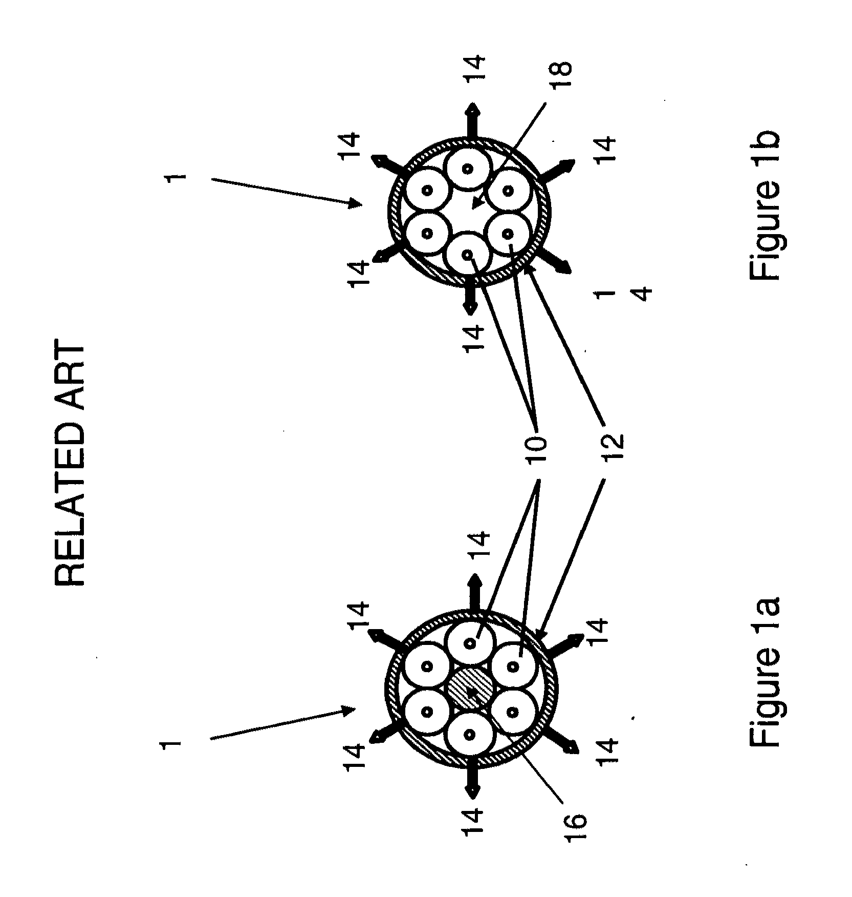
The use of a plurality of single optical fibers, however, limits the number of optical probes of this kind that may be distributed within the circumference of a probe housing due to the relatively large thickness of the cladding layer of the single optical fibers.
The assembly and alignment of such multiple fiber probes can be challenging.

Method used


Image

  • Multi-core low reflection lateral output fiber probe
  • Multi-core low reflection lateral output fiber probe
  • Multi-core low reflection lateral output fiber probe

Examples


Embodiment Construction

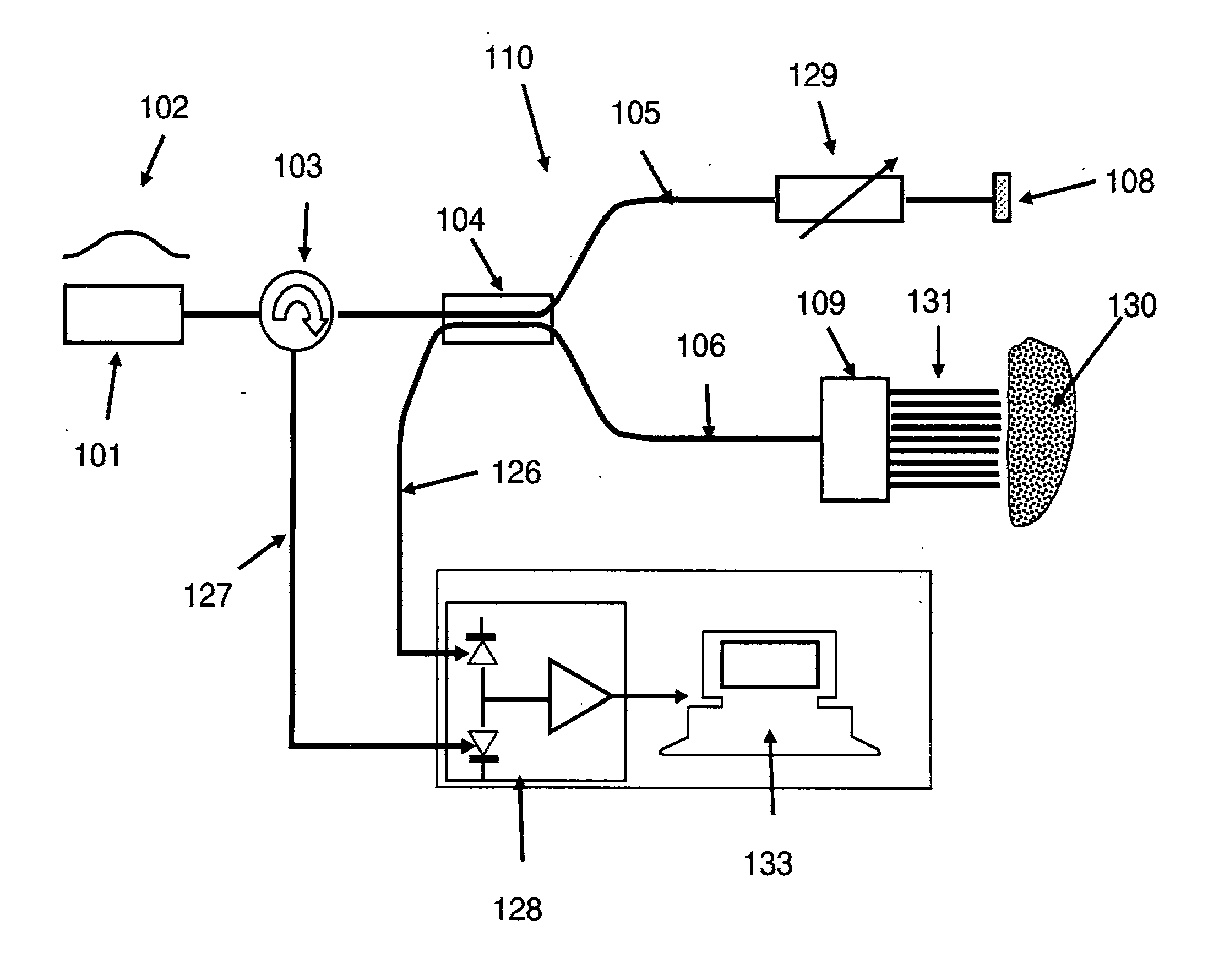
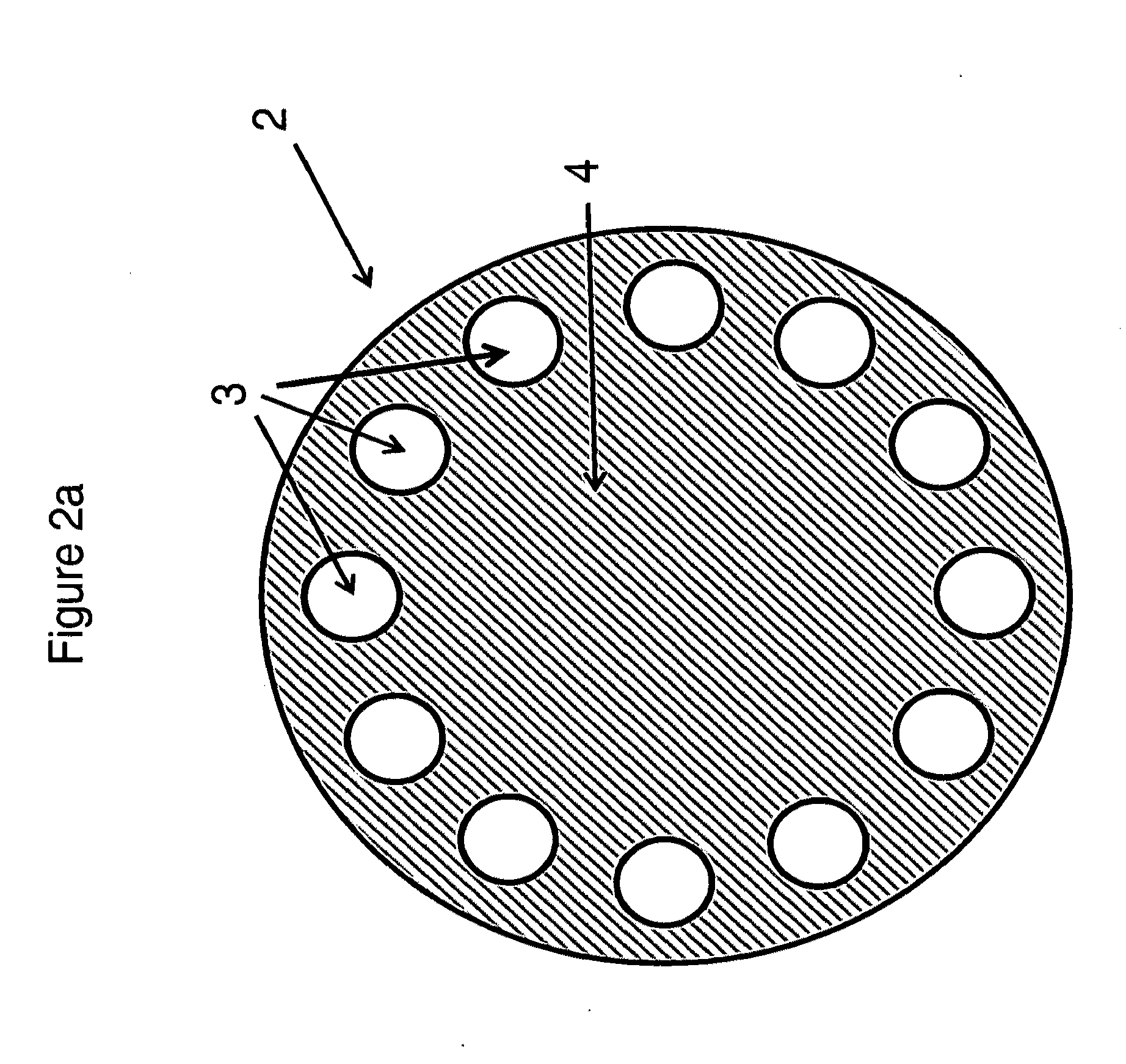
[0039]Referring now to the drawings, and more particularly to FIGS. 2-17, there are shown exemplary embodiments of the method and structures according to the present invention.

[0040]The invention described herein is directed to an optical probe including a multi-core optical fiber in which each of the cores and surrounding cladding act as a reduced reflection, lateral output optical probe.

[0041]Exemplary embodiments of the invention generally relate to a multi-core fiber probe, a system, and a method for minimizing reflection and preventing astigmatism in a fiber probe for use, for example, in a multiple-probe interferometer system. In particular, the exemplary embodiments of the invention relate to a multi-core fiber probe, system and method for minimizing reflection and preventing astigmatism in an optical emitting fiber.

[0042]As used herein, “optical emitting fibers” refer to optical fibers that are typically made of glass or a material having a higher dielectric constant than th...


PUM


Abstract

Multi-core optical fiber probe includes a multi-core optical fiber (and method of manufacturing the probe) including a plurality of cores adjacent a cladding material, and a plurality of angled reflectors disposed at a distal end of the cores. An angled reflector of the plurality of angled reflectors deflects light propagating in the core at a deflection angle that is different from an axis of light propagation in the core. Light propagating toward a distal end of the core of the multi-core probe is emitted, after reflection by the corresponding reflector, out of the multi-core optical fiber probe.

Description

CROSS-REFERENCE TO RELATED APPLICATIONS[0001]The present Application is related to and claims priority from co-pending provisional application 61 / 455,630, filed on Oct. 25, 2010, and incorporated herein by reference.BACKGROUND OF THE INVENTION[0002]1. Field of the Invention[0003]The present invention generally relates to an optical fiber probe made of a multi-core optical fiber.[0004]2. Description of the Related Art[0005]In medical diagnostics, there is a need to detect and characterize disease in blood vessels, the esophagus, the pulmonary, gastro-intestinal, and urinary systems and any other hollow anatomical volume accessible either naturally or via surgical methods.[0006]For example, in the detection and treatment of coronary artery disease, plaques, lesions and other vascular pathologies provide information to enable cardiologists to provide adequate therapy. Vulnerable plaques are a specific type of plaque that grows inside the artery and traps lipid within the arterial wall....

Claims


Application Information

Patent Timeline
IPC IPC(8): G01B9/02G02B17/00G02B6/00
CPCA61B1/00167G02B6/02042G02B6/262G01B9/02091G01B9/0207G01B9/02021G01B9/0205G01B9/02044
Inventor ALPHONSE, GERARD ARGANTCARLIN, DONALD BARRY
Owner ALPHONSE GERARD ARGANT
Learn More