Eureka AIR delivers breakthrough ideas for toughest innovation challenges, trusted by R&D personnel around the world.

Shower Plate Having Different Aperture Dimensions and/or Distributions

a technology of aperture dimensions and aperture distributions, applied in the field of shower plates, can solve the problems of affecting film thickness and film properties, unable to form perfect cylinders in the inner wall of the reaction chamber, and difficult to form thin films with desired properties stably, etc., to achieve high in-plane uniformity, reduce gas flow rate, and increase the thickness of depositing films

Active Publication Date: 2012-04-26
ASM JAPAN
View PDF52 Cites 6 Cited by
  • Summary
  • Abstract
  • Description
  • Claims
  • Application Information

AI Technical Summary

Benefits of technology

[0008]In an embodiment of the present invention, a plasma enhanced deposition apparatus, which is able to form a thin film having uniform properties, is provided. In an embodiment, a film having high in-plane uniformity can be formed by accommodating irregularities formed at or on an inner surface of the reaction chamber, relative to a perfectly cylindrical inner surface. In an embodiment, it can be achieved by using a specifically designed shower plate.
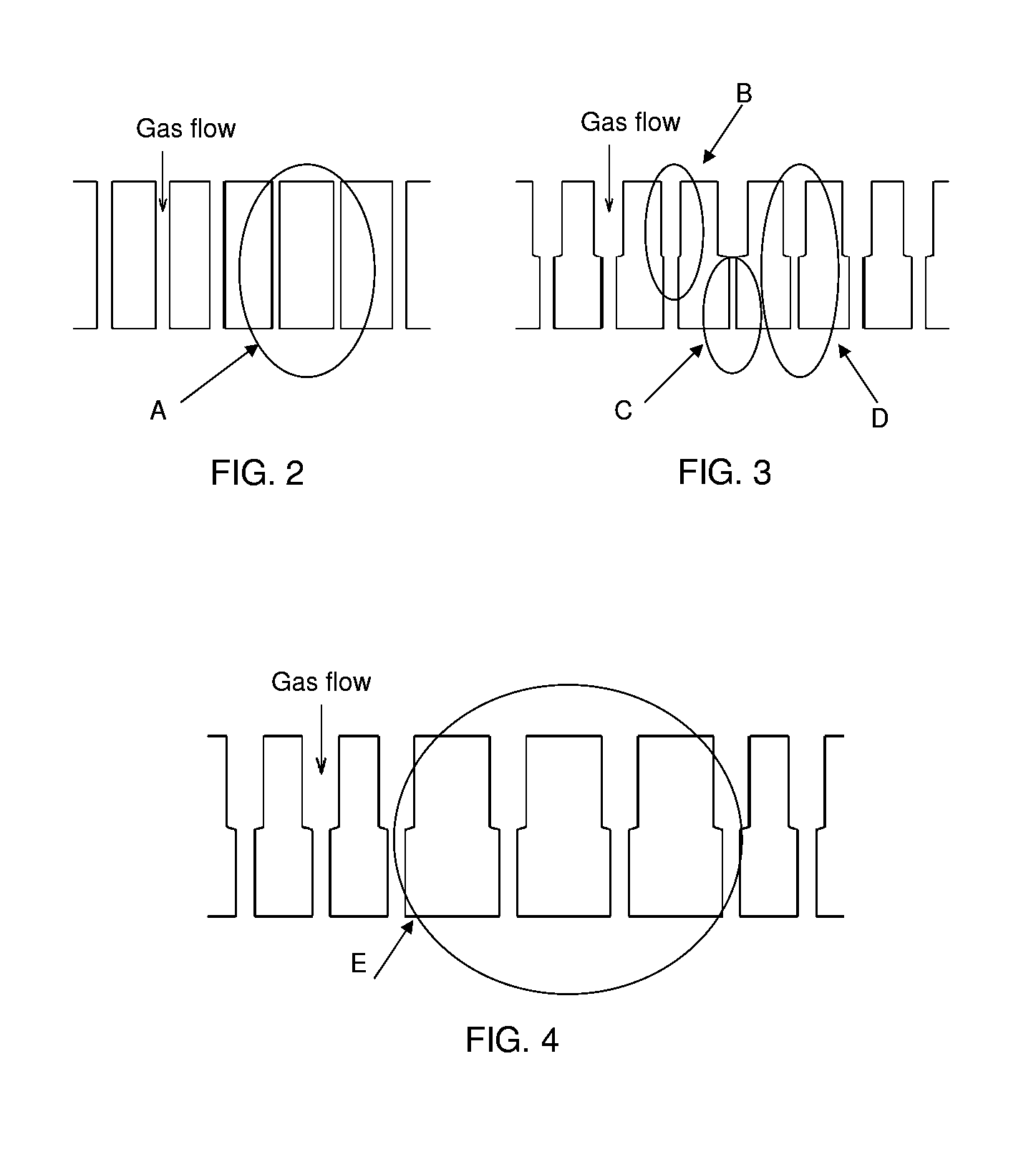
[0010](1) the size of the apertures within a selected position or positions of the shower plate is made smaller than that of other apertures, thereby increasing gas flow resistance or decreasing conductance of gas flow locally in the selected area(s), so as to compensate for localized plasma diffusion due to the irregularity of the inner surface of the reaction chamber; and / or

Problems solved by technology

However, conventional plasma CVD apparatuses have a problem in that it is difficult to form a thin film having desired properties stably with excellent controllability or reproducibility.
However, since the reaction chamber is equipped necessarily with a wafer transfer gate, a view port, etc., the inner wall of the reaction chamber cannot form a shape of a perfect cylinder and intrinsically forms a partially irregular shape.
At such irregularly shaped portions, due to the irregularity, a plasma is partially diffused and becomes non-uniform along a plane parallel to the front surface of the shower plate, thereby affecting film thickness and film properties.

Method used


Image

  • Shower Plate Having Different Aperture Dimensions and/or Distributions
  • Shower Plate Having Different Aperture Dimensions and/or Distributions
  • Shower Plate Having Different Aperture Dimensions and/or Distributions

Examples


example

[0056]An embodiment of the present invention will be explained with reference to the following example which is not intended to limit the present invention.

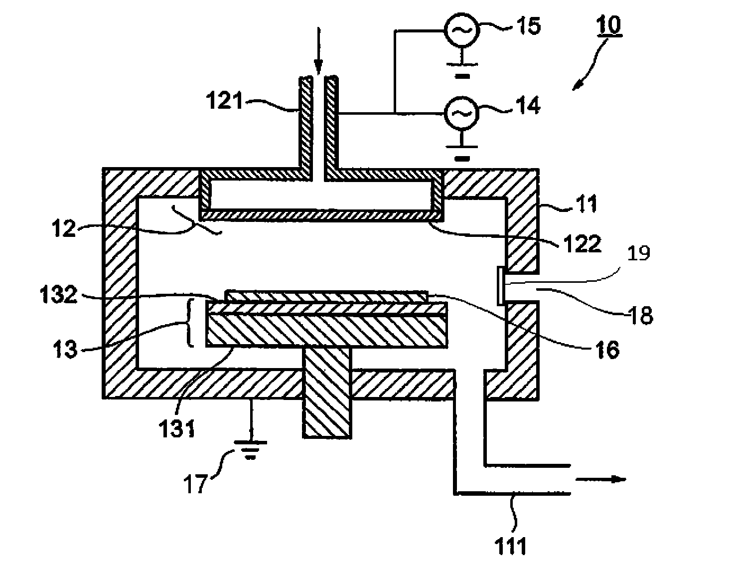
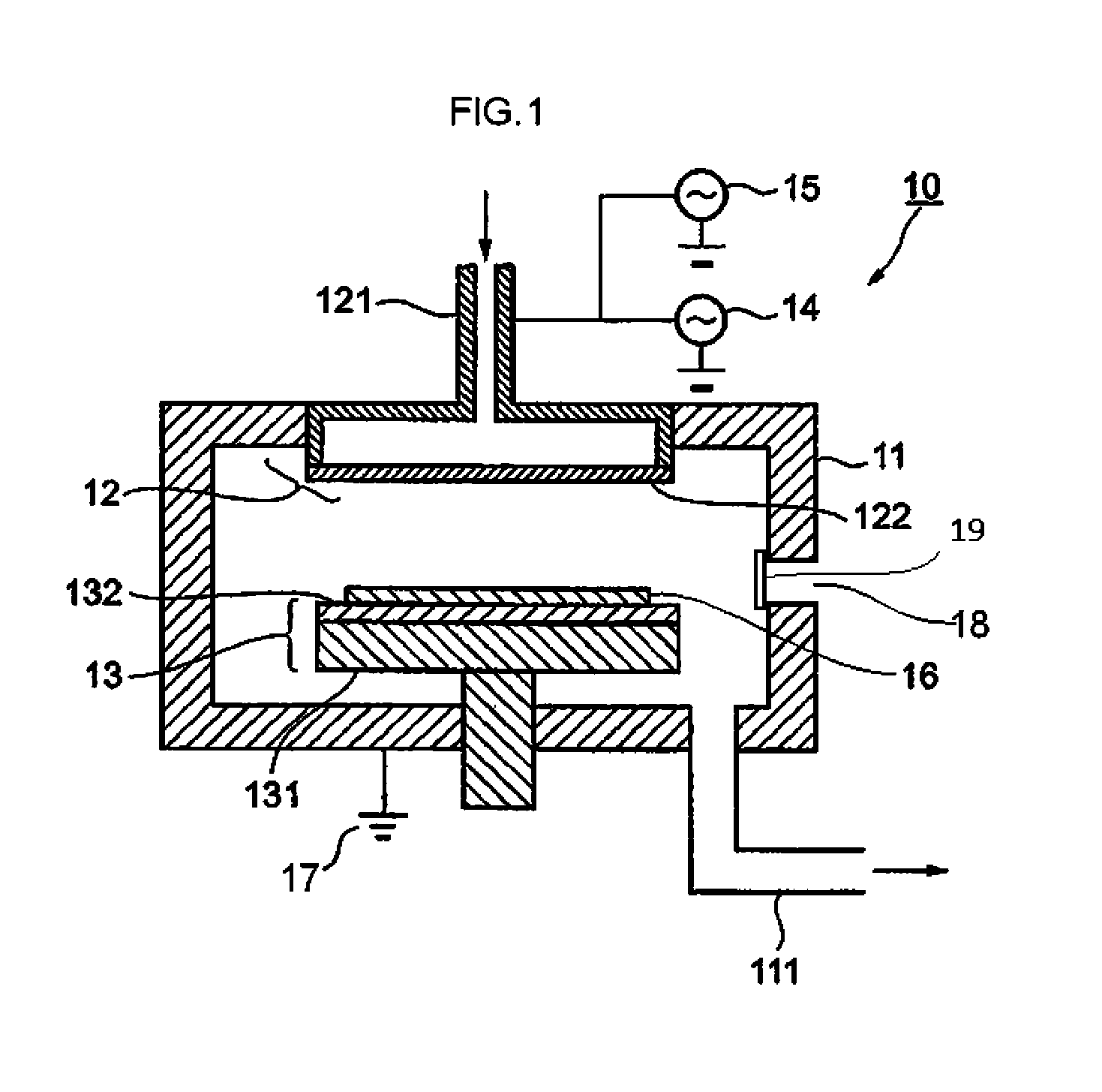
[0057]FIG. 1 shows a schematic view of one embodiment of the plasma CVD apparatus according to the present invention. This plasma CVD apparatus 10 comprises a vacuum (reaction) chamber 11, a first electrode 12 (showerhead) being provided at the top of the vacuum chamber 11 and insulated from the vacuum chamber 11, a second electrode 13 (susceptor) being provided inside the vacuum chamber 11 substantially parallel to the first electrode 12, and RF power sources 14 and 15 connected to the first electrode.

[0058]The vacuum chamber 11 has an opening at its lower portion and comprises an exhaust port 111 (exhaust duct) connected to an exhaust pump not shown. Additionally, the vacuum chamber 11 is grounded. The vacuum chamber 11 also has an opening 18 with a gate valve 19 on an inner side wall for wafer transfer.

[0059]The first electrod...


PUM

PropertyMeasurementUnit
angleaaaaaaaaaa
angleaaaaaaaaaa
angleaaaaaaaaaa

Abstract

A shower plate is adapted to be attached to the showerhead and includes a front surface adapted to face the susceptor; and a rear surface opposite to the front surface. The shower plate has multiple apertures each extending from the rear surface to the front surface for passing gas therethrough in this direction, and the shower plate has at least one quadrant section defined by radii, wherein the one quadrant section has an opening ratio of a total volume of openings of all the apertures distributed in the section to a total volume of the one quadrant section, which opening ratio is substantially smaller than an opening ratio of another quadrant section of the shower plate.

Description

BACKGROUND[0001]1. Field of the Invention[0002]The present invention generally relates to a plasma deposition apparatus used in a semiconductor manufacturing process; particularly to a shower plate provided in the apparatus.[0003]2. Description of the Related Art[0004]A conventional plasma CVD apparatus possesses a first and a second electrode disposed parallel to each other inside a vacuum chamber; the first electrode has a hollow structure for introducing source gases into the vacuum chamber and has a shower plate removably attached in its bottom face; in the shower plate, many gas outlet holes or apertures are formed.[0005]A conventional shower plate is disk-shaped and has many gas outlet apertures (e.g., 3,000 to 5,000) of a given diameter being formed in an arrangement adapted to pass completely through to the reverse face of the shower plate from its front face. Additionally, in the conventional shower plate, apertures are symmetrically distributed along its axis typically in ...

Claims


Application Information

Patent Timeline
Patent Type & Authority Applications(United States)
IPC IPC(8): C23C16/455C23C16/52C23C16/00
CPCC23C16/45525C23C16/45565H01J37/32449H01J37/3244C23C16/50
Inventor AIDA, KOEIBABA, TOMOYUKI
Owner ASM JAPAN
Why Eureka
Eureka Blog
Learn More