Power supply with single stage converter for performing power factor correction and resonant conversion

a technology of power factor correction and resonant conversion, applied in the field of power supply, can solve the problems of boosting power loss and inflating cost, and achieve the effects of reducing cost, reducing circuit elements, and reducing power loss

Active Publication Date: 2012-05-03
DELTA ELECTRONICS INC
View PDF14 Cites 25 Cited by
  • Summary
  • Abstract
  • Description
  • Claims
  • Application Information

AI Technical Summary

Benefits of technology

[0004]An aspect of the invention is to provide a power supply with a single stage converter for performing power factor correction and resonant conversion to lower power loss, descend cost, or reduce the number of circuit elements.

Problems solved by technology

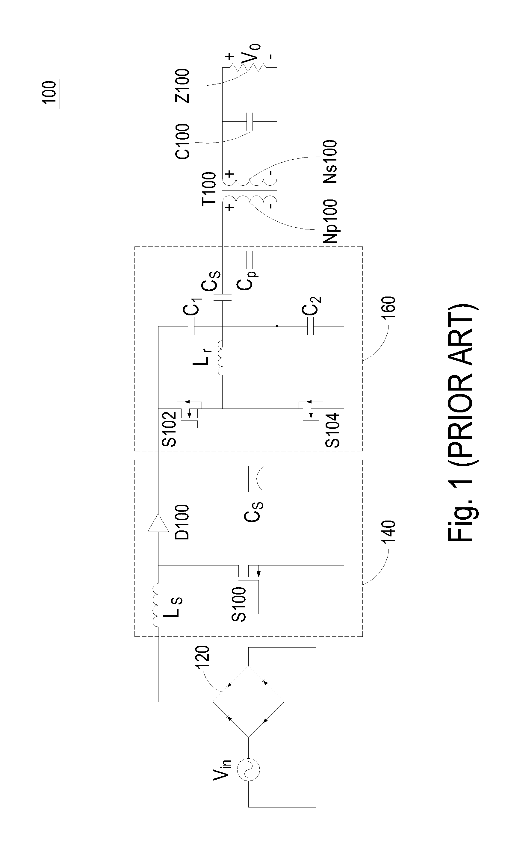
Also, because the two-stage converter is employed to achieve the power conversion for the power supply, the number of the circuit elements of the power supply is increased, thereby inflating the cost and boosting power loss.

Method used


Image

  • Power supply with single stage converter for performing power factor correction and resonant conversion
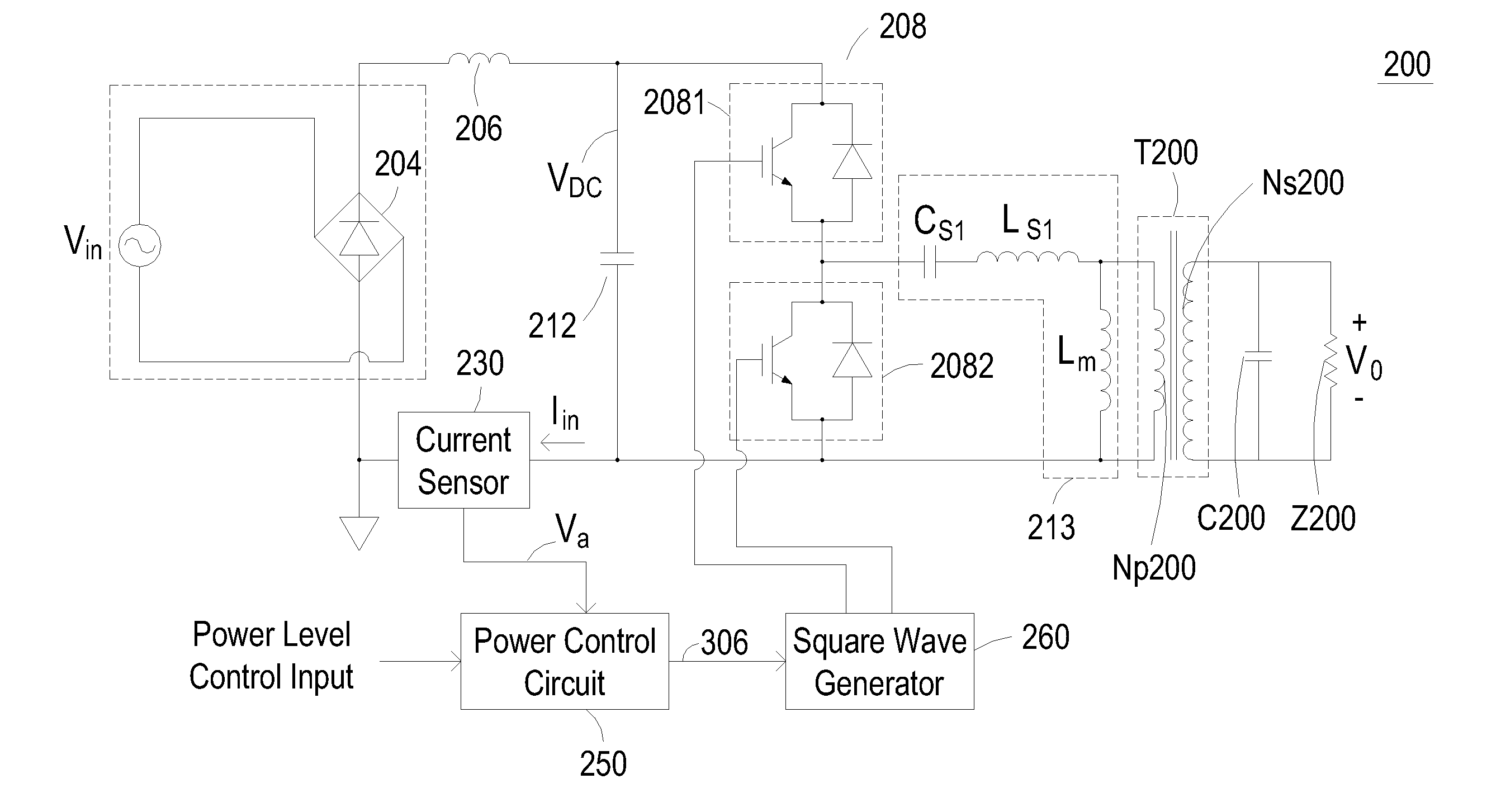
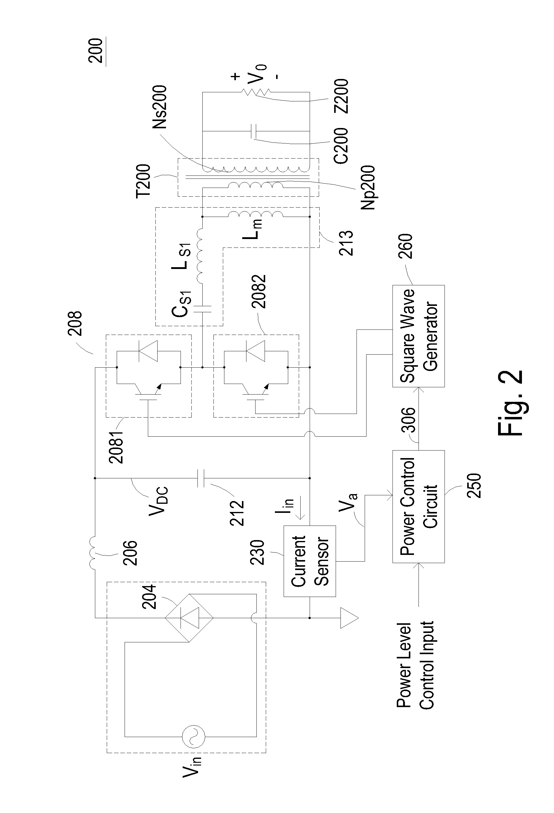
  • Power supply with single stage converter for performing power factor correction and resonant conversion
  • Power supply with single stage converter for performing power factor correction and resonant conversion

Examples


third embodiment

[0020]FIG. 6 shows the circuit blocks of a power supply 600 according to the invention. The power supply 600 as shown in FIG. 6 is configured to output a DC voltage Vo with a pair of rectifying diodes D602, D604 placed on the secondary side Ns200 of the transformer T200. The rectifying diodes D602 and D604 are used to rectify the AC voltage induced across the secondary side Ns200 of the transformer T200 into a half-wave rectified DC voltage.

[0021]FIG. 7 shows the circuit blocks of a power supply 700 according to a fourth embodiment of the invention. Compared to the third embodiment of FIG. 6, the power supply 700 shown in FIG. 7 includes an additional DC-DC buck converter 702 which is placed between the output capacitor C200 and the load Z200. The DC-DC buck converter 702 is used to descend the output voltage Vo to a lower DC voltage for powering the load Z200.

fifth embodiment

[0022]FIG. 8 shows the circuit blocks of a power supply 800 according to the invention. The power supply 800 shown in FIG. 8 includes an additional hold-up time extension circuit 802 which is placed between the output capacitor C200 and the DC-DC buck converter 702. The hold-up time extension circuit 802 is used to extend the hold-up time of the output capacitor C200.

[0023]In conclusion, one embodiment of the invention provides a power supply with a single stage converter for performing power factor correction and resonant conversion. The single stage converter is consisted of a switch circuit, a resonant circuit, a power control circuit, and a square wave generator. The switch circuit includes at least one control switch, and the resonant circuit includes a LLC resonant tank such as a series resonant circuit or a parallel resonant circuit. The power control circuit is implemented by a proportional differential circuit, which is consisted of, for example, a power amplifier configure...


PUM


Abstract

The invention discloses a power supply having a single stage converter for performing power factor correction to reduce high-frequency harmonics in the input current and performing resonant conversion to achieve zero-voltage switching or zero-current switching for power conversion. The inventive single stage converter includes a switching circuit, a resonant circuit, a power control circuit, and a square wave generator. The switching circuit includes at least one switch and the resonant circuit includes a LLC resonant tank. The power control circuit includes a proportional differential circuit such as a power amplifier configured in a negative feedback topology, and the square wave generator is configured to generate driving signals based on the frequency modulation control signal generated by the comparison of the sensed input current and a user-defined power level input, thereby allowing the square wave generator to regulate the switching operation of the switching circuit.

Description

FIELD OF THE INVENTION[0001]The invention relates to a power supply, and more particularly to a power supply with a single stage converter for performing power factor correction and resonant conversion.BACKGROUND OF THE INVENTION[0002]The conventional high-voltage power supply generally employs a two-stage converter to convert an input voltage into an output voltage. As shown in FIG. 1, a power supply 100 is configured to convert an AC voltage Vin into an output voltage Vo. The power supply 100 includes a bridge rectifier 120, a power factor correction converter 140, a resonant converter 160, a transformer T100, and an output capacitor C100. The output voltage Vo is used to drive a load Z100. The bridge rectifier 120 is configured to rectify the AC voltage Vin into a full-wave rectified DC voltage. The power factor correction converter 140 is connected to the output end of the bridge rectifier 120 and includes a boost choke Ls, a control switch S100, a diode D100, and a filtering ca...

Claims


Application Information

Patent Timeline
Patent Type & Authority Applications(United States)
IPC IPC(8): H02M3/335
CPCH02M1/4258H02M3/3376H02M2001/0054Y02B70/126Y02B70/1433Y02B70/1491Y02P80/112H02M1/0054Y02B70/10Y02P80/10
Inventor TANG, PAK-CHUENCHING, KWONG-MINGPOON, CHUNG-HEI
Owner DELTA ELECTRONICS INC
Why Eureka
Try Eureka