

Method for applying a shrink label to an article, a shrink label and a shrink label material
a technology of shrink label and shrink label, applied in the direction of seals, identification means, instruments, etc., can solve the problems of preventing the applicability of labels for all applications, low shrinkage performance, and strong force on the adhesive joints, etc., to achieve easy transportation, high shrink demand labels, and simple and convenient use.
- Summary
- Abstract
- Description
- Claims
- Application Information
AI Technical Summary
Benefits of technology
Problems solved by technology
Method used
Image

Examples
Embodiment Construction
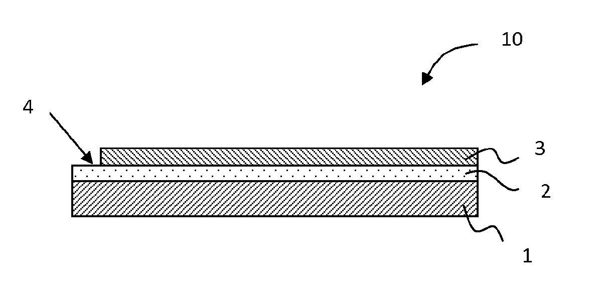
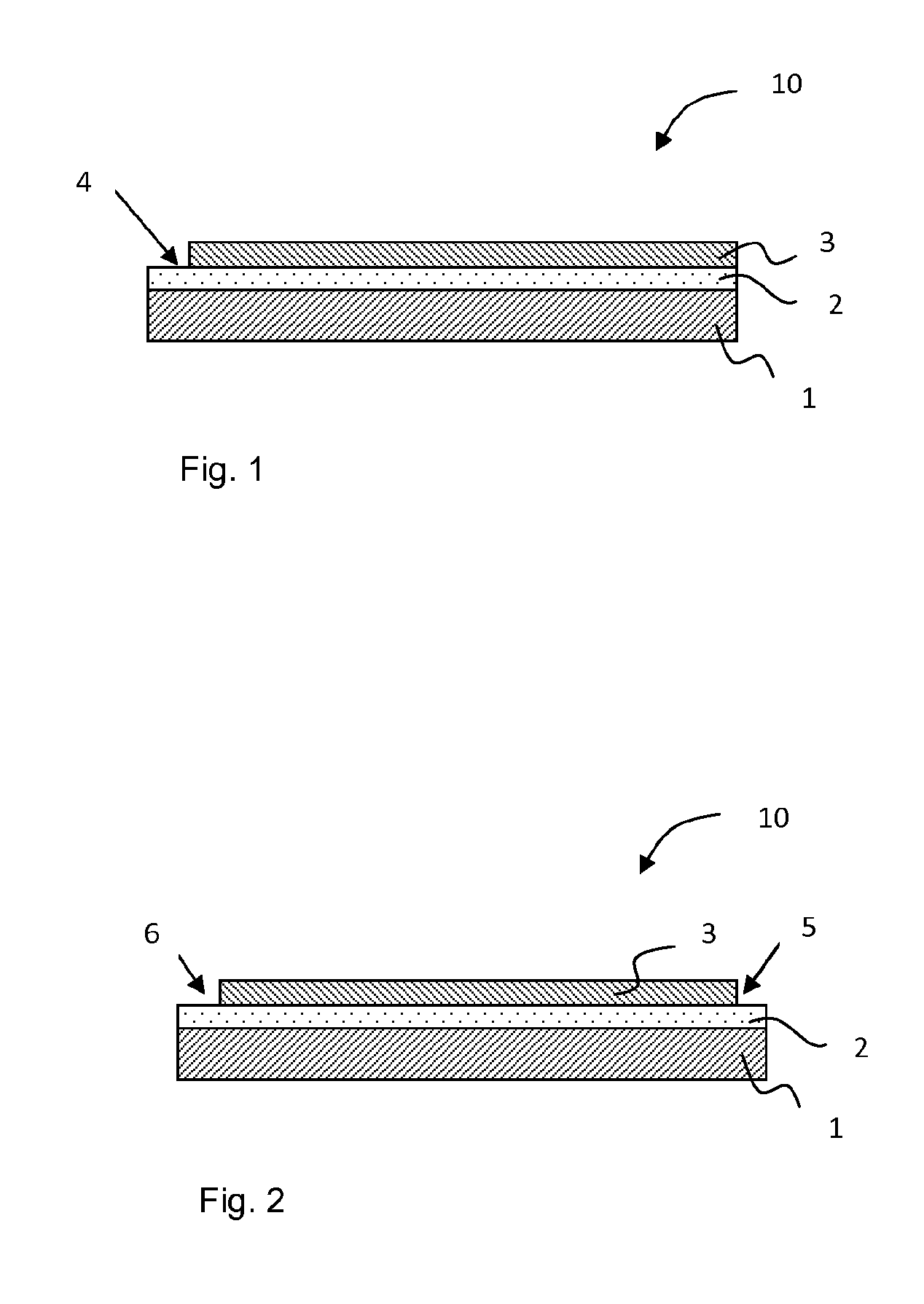
[0033]The invention will be described with reference to FIGS. 1 and 2, which show a cross-sectional view of the shrink labels according to the invention. The shrink label 10 comprises a machine direction oriented polyolefin shrink film 1, an adhesive layer 2 and a printing ink layer 3. One surface of the polyolefin film 1 is fully coated with the activatable polyurethane adhesive. After the formation of the adhesive layer 2, the printing ink layer 3 is formed over the adhesive layer except for at least one edge 4, 5, 6 of the film reserved for a seam to form a sleeve.
[0034]FIG. 1 illustrates the shrink label structure applicable in the case of the pre-formed label sleeve. The non-activated adhesive layer 2 is printed except for one edge 4 reserved for an overlapping joint to form a sleeve. After printing, the adhesive is activated in the non-printed edge 4 and the edge 4 is bonded to the opposite edge of the label to form the pre-formed sleeve, i.e. a tube or a cylinder, which can b...
PUM
| Property | Measurement | Unit |
|---|---|---|
| shrink | aaaaa | aaaaa |
| temperatures | aaaaa | aaaaa |
| shrinkage | aaaaa | aaaaa |
Abstract
Description
Claims
Application Information