Magnesium doping in barriers in multiple quantum well structures of iii-nitride-based light emitting devices

Inactive Publication Date: 2012-05-03
RGT UNIV OF CALIFORNIA
View PDF5 Cites 14 Cited by
  • Summary
  • Abstract
  • Description
  • Claims
  • Application Information

AI Technical Summary

Benefits of technology

[0014]This is accomplished by introducing a bis(cyclopentadienyl)magnesium (Cp2Mg) flow during growth of one or more of the barriers, using metal organic chemical vapor deposition (MOCVD), in order to dope the barrier with Mg. The

Problems solved by technology

However, the use of AlGaN barriers requires a higher forward voltage and results in the unequal d

Method used


Image

  • Magnesium doping in barriers in multiple quantum well structures of iii-nitride-based light emitting devices
  • Magnesium doping in barriers in multiple quantum well structures of iii-nitride-based light emitting devices
  • Magnesium doping in barriers in multiple quantum well structures of iii-nitride-based light emitting devices

Examples


Embodiment Construction

[0021]In the following description of the preferred embodiment, reference is made to the accompanying drawings which form a part hereof, and in which is shown by way of illustration a specific embodiment in which the invention may be practiced. It is to be understood that other embodiments may be utilized and structural changes may be made without departing from the scope of the present invention.

[0022]Overview

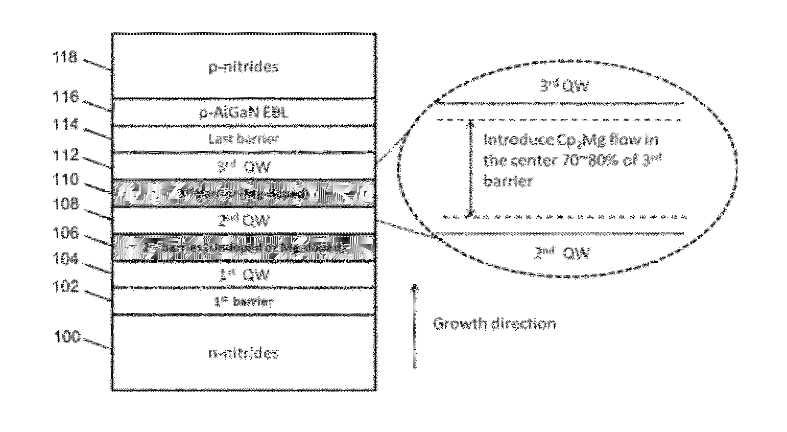
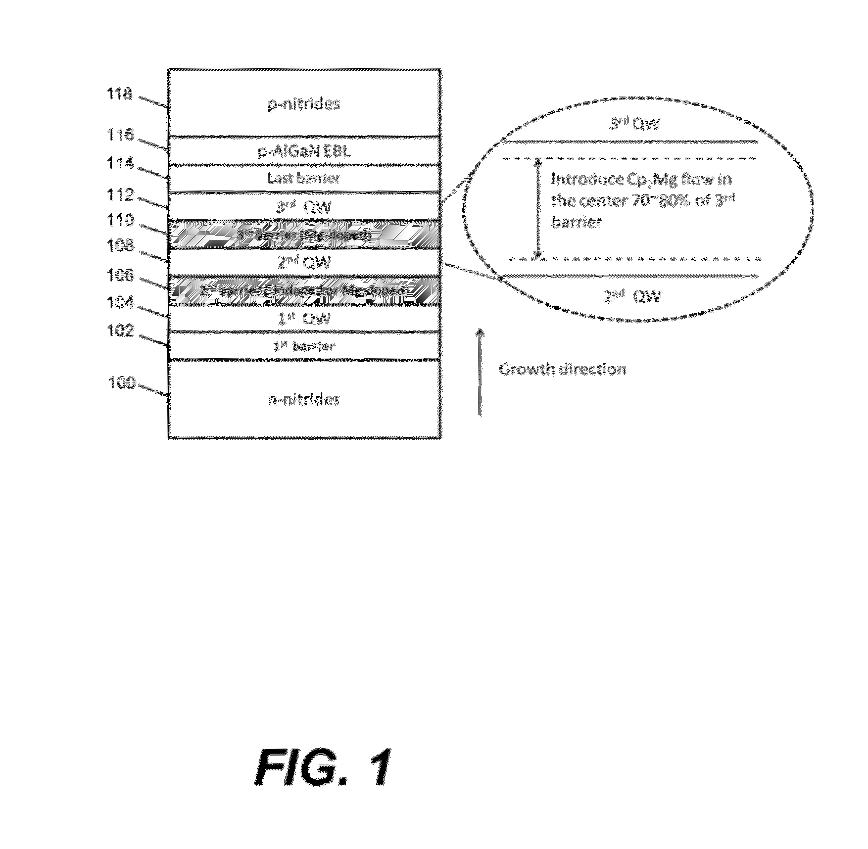
[0023]The present invention provides Mg doping in barriers of QWs to improve hole transport and carrier distribution between the QWs. In one embodiment, the Mg doping is performed on III-nitride-based light emitting devices, such as laser diodes, light-emitting diodes and superluminescence diodes, grown on semipolar or nonpolar bulk GaN substrates and having long-wavelength MQW structures in their active or light emitting regions, although the present invention is applicable to other light emitting devices as well.

[0024]Technical Description

[0025]Conventional MQW light emittin...


PUM


Abstract

A III-nitride-based light emitting device having a multiple quantum well (MQW) structure and a method for fabricating the device, wherein at least one barrier in the MQW structure is doped with magnesium (Mg). The Mg doping of the barrier is accomplished by introducing a bis(cyclopentadienyl)magnesium (Cp2Mg) flow during growth of the barrier using metalorganic chemical vapor deposition (MOCVD). The barriers of the MQW structure may be undoped, fully Mg-doped or partially Mg-doped. When the barrier is partially Mg-doped, only portions of the barrier are Mg-doped to prevent Mg diffusion into quantum wells of the MQW structure. The Mg-doped barriers preferably are high Al composition AlGaN barriers in nonpolar or semipolar devices.

Description

CROSS REFERENCE TO RELATED APPLICATION[0001]This application claims the benefit under 35 U.S.C. Section 119(e) of the following co-pending and commonly-assigned application:[0002]U.S. Provisional Patent Application Ser. No. 61 / 405,416, filed on Oct. 21, 2010, by Chia-Yen Huang, Shuji Nakamura, Steven P. DenBaars, and James S. Speck, entitled “MAGNESIUM DOPING IN BARRIERS IN MULTIPLE QUANTUM WELL STRUCTURES OF III-NITRIDE-BASED LIGHT EMITTING DEVICES,” attorneys' docket number 30794.395-US-P1 (2011-171-1);[0003]which application is incorporated by reference herein.BACKGROUND OF THE INVENTION[0004]1. Field of the Invention[0005]The invention is related to the field of III-nitride-based light emitting devices.[0006]2. Description of the Related Art[0007](Note: This application references a number of different publications as indicated throughout the specification by one or more reference numbers within brackets, e.g., [x]. A list of these different publications ordered according to the...

Claims


Application Information

Patent Timeline
IPC IPC(8): H01L33/06H01S5/343H01L21/18
CPCH01L33/007H01L33/025H01L33/06H01L33/08H01S5/2009H01S5/3063H01S5/309H01S5/34333B82Y20/00
Inventor HUANG, CHIA-YENNAKAMURA, SHUJIDENBAARS, STEVEN P.SPECK, JAMES S.
Owner RGT UNIV OF CALIFORNIA
Why Eureka
Try Eureka