Driving method for piezoelectric vibrator, and dust removing device and ultrasonic motor using the driving method

Inactive Publication Date: 2012-05-10
CANON KK
View PDF1 Cites 18 Cited by
  • Summary
  • Abstract
  • Description
  • Claims
  • Application Information

AI Technical Summary

Benefits of technology

[0013]The present invention has been made in view of the above-mentioned problems, and it is an object thereof to provide a driving method for a piezoelectric vibrator, which is capable of carrying out adjustment in accord

Problems solved by technology

H11-253900, however, a sound pressure sensor is provided for detecting deterioration of an ultrasonic vibrator, thus causing a problem in that the size of the device increases to increase manufacturing cost.
Detecting the deterioration of the ultrasonic vibrator by using the vibration detection piezoelectric element formed of the same material as that of the driving piezoelectric element, however, causes the following problem.
It is conceivable, however,

Method used


Image

  • Driving method for piezoelectric vibrator, and dust removing device and ultrasonic motor using the driving method
  • Driving method for piezoelectric vibrator, and dust removing device and ultrasonic motor using the driving method
  • Driving method for piezoelectric vibrator, and dust removing device and ultrasonic motor using the driving method

Examples


embodiment 1

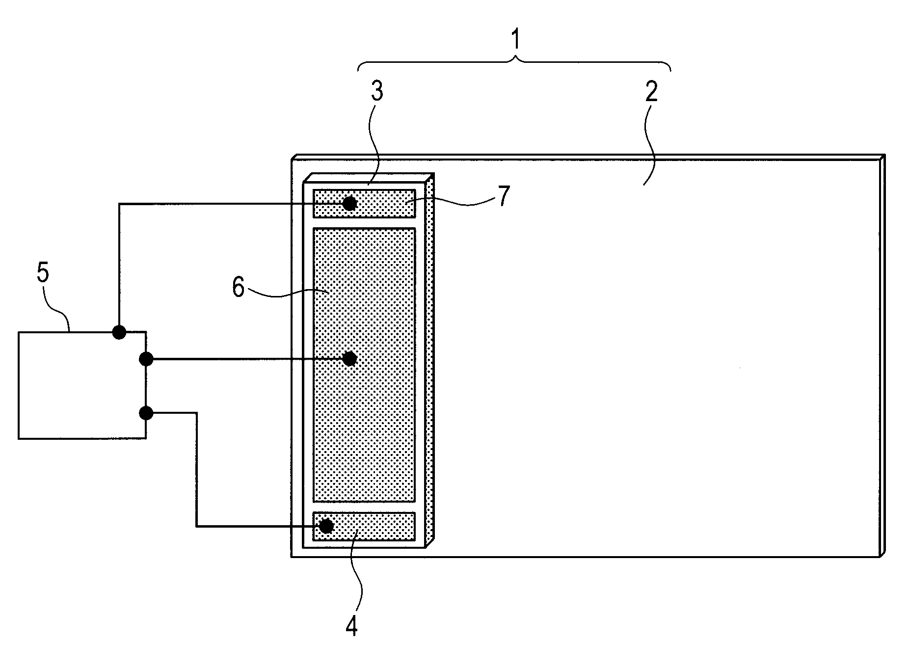
[0036]Referring to FIG. 1, an embodiment 1 of the present invention is described by way of a configuration example of a piezoelectric vibrator for use in a dust removing device for removing dust adhering onto an optical element of a single lens reflex camera to which the present invention is applied.

[0037]A piezoelectric vibrator 1 includes an optical element 2 and a piezoelectric element 3 bonded onto the optical element.

[0038]The piezoelectric element 3 has a ground electrode (not shown) provided on the entire surface onto which the optical element 2 is bonded.

[0039]The ground electrode is electrically connected via a via electrode passing through the piezoelectric element 3 to a surface ground electrode 4 disposed on a part of the front surface opposite to the ground electrode. The ground electrode is further wired to a ground terminal of a driving circuit 5.

[0040]The most part of the front surface of the piezoelectric element 3 is occupied by a driving voltage application electr...

second embodiment

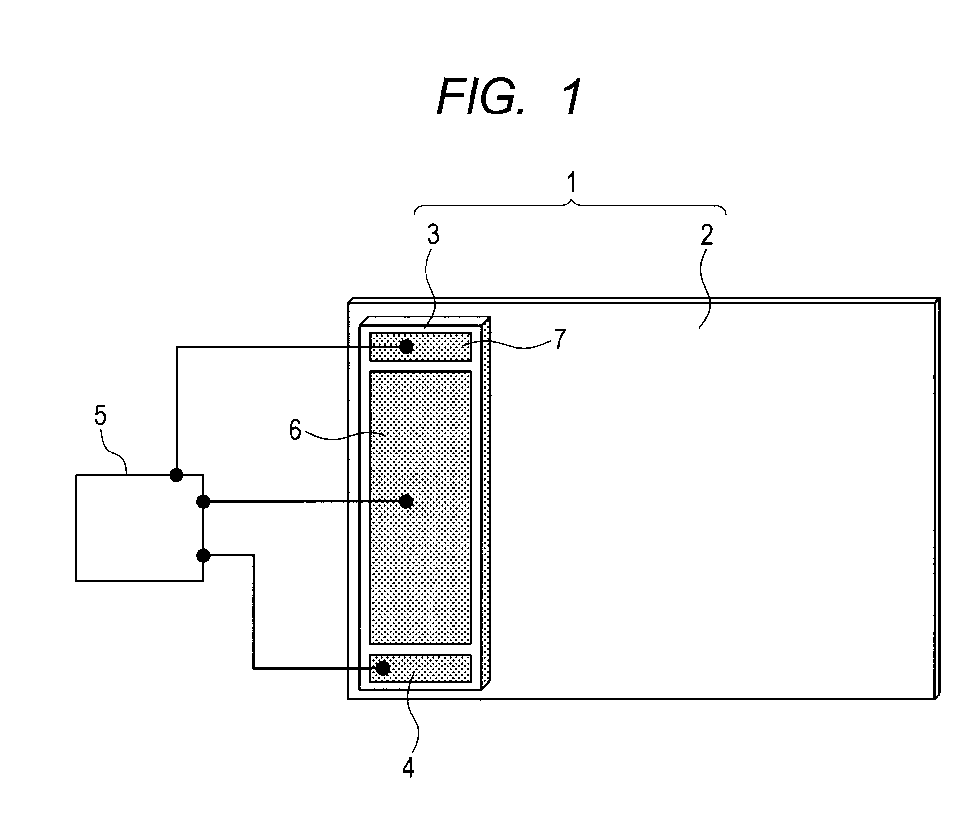
[0074]Referring to FIG. 2, a second embodiment of the present invention is described by way of a configuration example of a piezoelectric vibrator for use in a dust removing device for removing dust adhering onto an optical element of a single lens reflex camera in the form different from the first embodiment.

[0075]The second embodiment is a modified example of the first embodiment, in which a piezoelectric vibrator of FIG. 2 is also a modification of the piezoelectric vibrator of FIG. 1. Accordingly, the difference from the first embodiment and FIG. 1 is mainly described here, and members of FIG. 2 denoted by the same reference numerals as those of FIG. 1 have the features similar to those described above with reference to FIG. 1. In FIG. 2, the output of the detection electrode 7 is connected to the surface ground electrode 4 via a current detection unit 8, such as a current probe.

[0076]The current detection unit 8 has so extremely small internal impedance that the detection elect...

third embodiment

[0097]Referring to FIG. 3, a third embodiment of the present invention is described by way of a configuration example of a piezoelectric vibrator for use in a dust removing device for removing dust adhering onto an optical element of a single lens reflex camera in the form different from the above-mentioned respective embodiments.

[0098]In the first and second embodiments, the variations in mechanical resistance of the piezoelectric vibrator and the variations in piezoelectric characteristic of the piezoelectric element are detected based on the output of the detection piezoelectric element, which is provided separately from the driving piezoelectric element.

[0099]In the third embodiment, unlike the first and second embodiments, the variations in mechanical resistance of the piezoelectric vibrator and the variations in piezoelectric characteristic of the piezoelectric element are detected based on a current of the driving piezoelectric element flowing when an alternating voltage is a...


PUM


Abstract

A driving method for a piezoelectric vibrator including a driving piezoelectric element and a detection piezoelectric element formed of the same material as a material of the driving piezoelectric element, for driving the piezoelectric vibrator by applying, to the driving piezoelectric element, an alternating voltage having a frequency close to a resonance frequency of the piezoelectric vibrator, the driving method including, in the case where it is detected based on variations in output detected from the detection piezoelectric element that at least one of variations in mechanical resistance of the piezoelectric vibrator and variations in piezoelectric characteristic of a piezoelectric element have occurred, applying an alternating voltage adjusted in accordance with the variations in mechanical resistance of the piezoelectric vibrator and/or the variations in piezoelectric characteristic of the piezoelectric element, to thereby adjust an electrical input to the piezoelectric vibrator to suppress variations in vibration amplitude of the piezoelectric vibrator.

Description

BACKGROUND OF THE INVENTION[0001]1. Field of the Invention[0002]The present invention relates to a driving method for a piezoelectric vibrator, and more particularly, to a driving method for a piezoelectric vibrator for use in an ultrasonic motor to be used in autofocus driving of a single lens reflex camera, for use in a dust removing device for removing dust adhering onto an optical element of a single lens reflex camera, or for other similar uses.[0003]2. Description of the Related Art[0004]Conventional examples of a device using a piezoelectric vibrator constituted by a piezoelectric element are an ultrasonic washer (see Japanese Patent Application Laid-Open No. H11-253900) and a dust removing device (see US 2009 / 207493 A1), or the like.[0005]In those devices, the piezoelectric vibrator is caused to vibrate by applying the piezoelectric element with an alternating voltage having a frequency close to the resonance frequency of mechanical vibration of the piezoelectric vibrator, a...

Claims


Application Information

Patent Timeline
IPC IPC(8): F28G7/00H02N2/06H01L41/09
CPCB06B1/0261B06B2201/55H02N2/0075H01L41/042H10N30/802H04N23/52H04N23/811
Inventor KANAZAWA, HAJIME
Owner CANON KK
Why Eureka
Try Eureka