

Photovoltaic modules with polypropylene based backsheet
- Summary
- Abstract
- Description
- Claims
- Application Information
AI Technical Summary
Benefits of technology
Problems solved by technology
Method used
Image

Examples
example 1
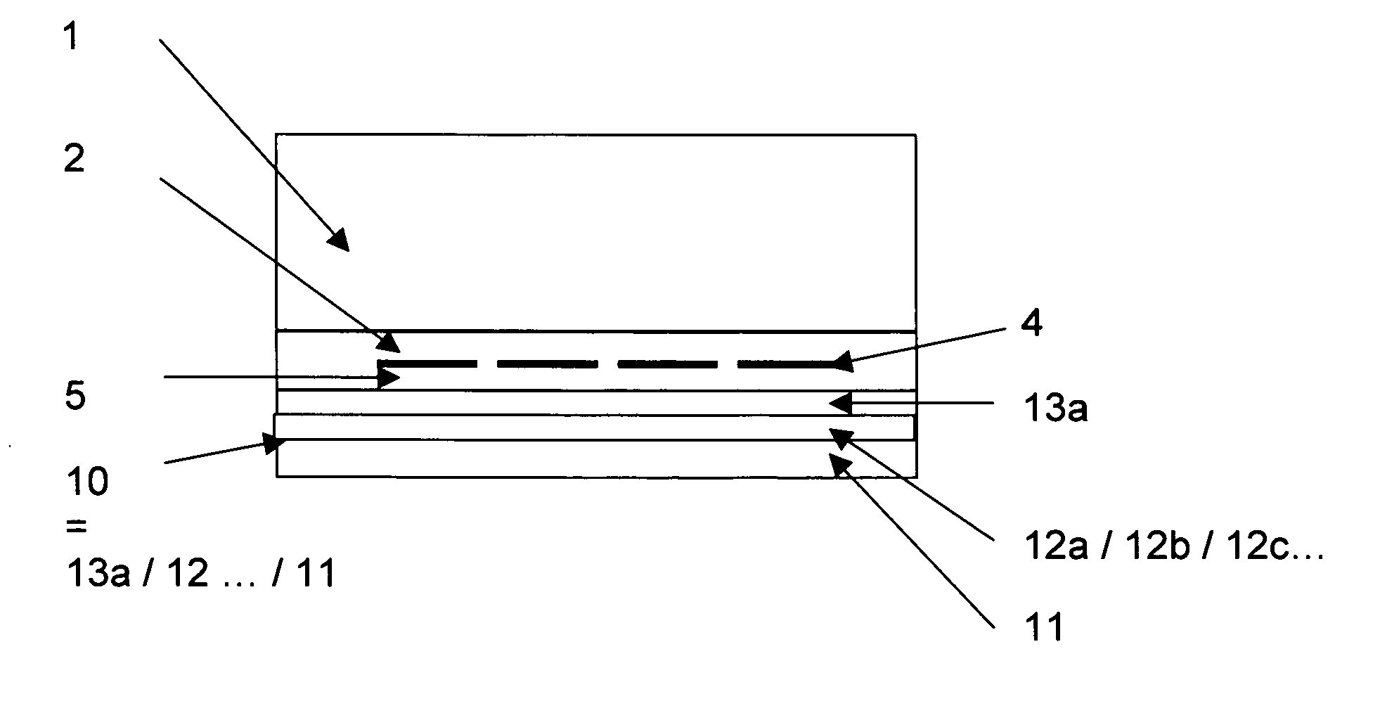
Coextruded or Colaminated Backsheet Foil (10) Consisting of a FPP layer (11) with a higher melting temperature than the module lamination temperature and a FPP Layer (13) with Improved Adhesion to Eva Adhesive Film (5)—FIG. 1
[0168]The following backsheet is obtained by coextrusion:[0169]Layer 1 (11)=550 μm thick film with following composition: Hifax CA 12 A: 100 parts, with TiO2 Kronos 2220: 10 parts; Chimassorb 2020: 0.8 parts; Tinuvin 770: 0.2 parts; Chimassorb 81: 0.2 parts; Irgastab FS301: 0.3 parts.[0170]Layer 2 (13)=50 μm thick film with following composition: Adsyl 5C 30 F (from LyondellBasell): 50 parts; Exact 8201 VLDPE (from Dexplastomer): 50 parts; TiO2 Kronos 2220: 5 parts; Chimassorb 2020: 0.8 parts; Tinuvin 770: 0.2 parts; Chimassorb 81: 0.2 parts, Irgastab FS301: 0.3 parts.
Layer 1 and 2 are produced in one step by coextrusion (manifold extrusion die).
[0171]Hifax CA 12 A is a reactor blend of PP homopolymer and EPR and has a melting temperature of 163° C. (MTM 15902),...
example 2
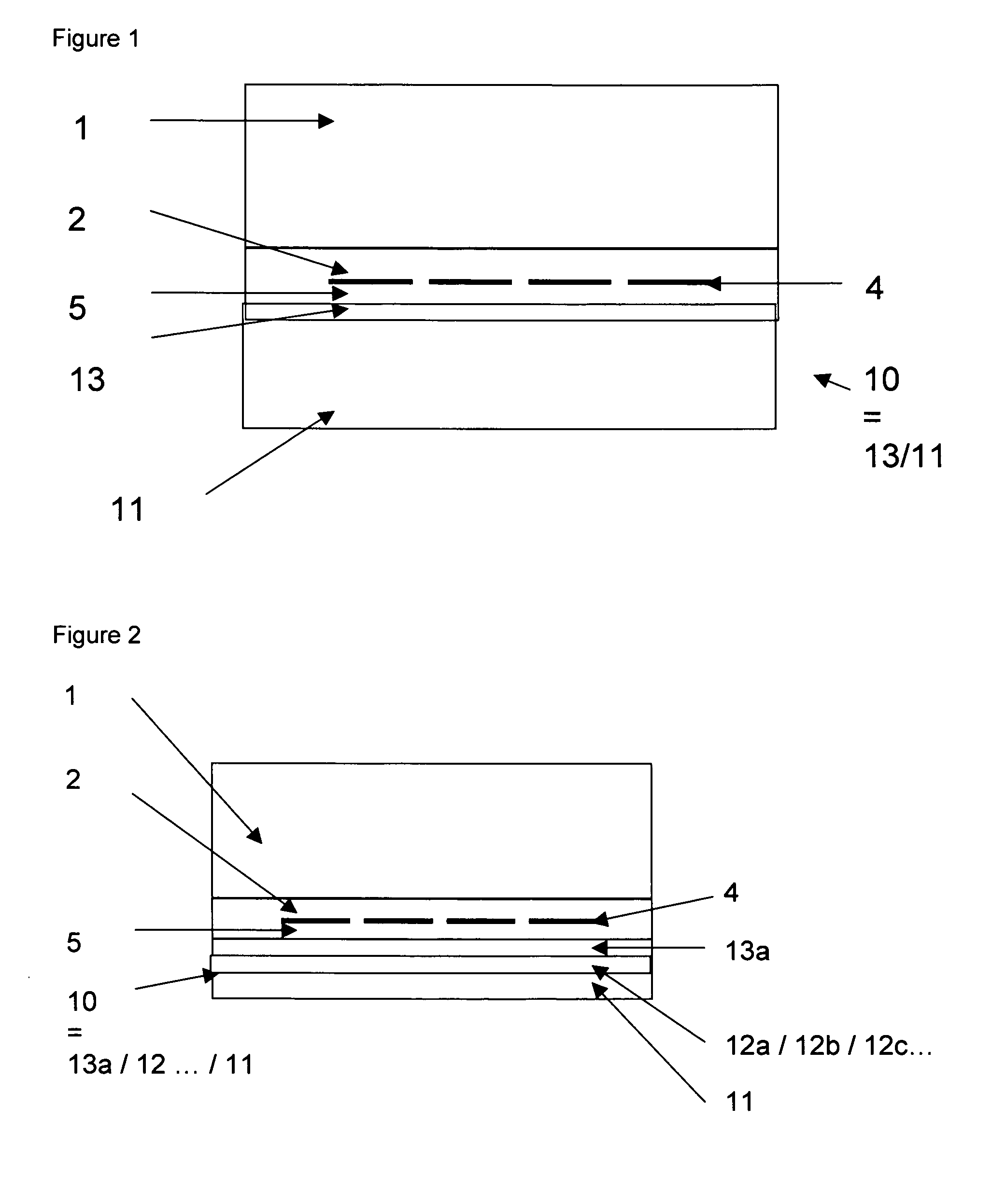
Backsheet with Primer Layer (13a)—FIG. 2
[0188]It has been observed that the adhesion between FPP backsheet (10) and EVA adhesive (5) may become low after storage e.g. in humid conditions, resulting in extreme cases to an adhesion value between FPP backsheet (10) and EVA adhesive layer (5) as low as the intrinsic adhesion value (typically 12 N / cm).
[0189]After extensive work and research, the reliability of the adhesion of the backsheet (10) of this invention to EVA adhesive layer (5) of e.g. the type Etimex 486.10, has been improved by coextrusion or colamination of the FPP foil (11) with a “primer” layer (13a) which shows intrinsic adhesion with the EVA adhesive layer (5).
[0190]Therefore, one produces by e.g. coextrusion and lamination the following multi-layer film:[0191]Layer 1 (13a)=10 μm thick layer based on EVA (Polyethylene-Vinyl Acetate) with e.g. 9% Vinyl Acetate Copolymer (e.g. EVA 1010VN3 from Total Petrochemicals), with pigments, possibly functional particles and additive...
example 3
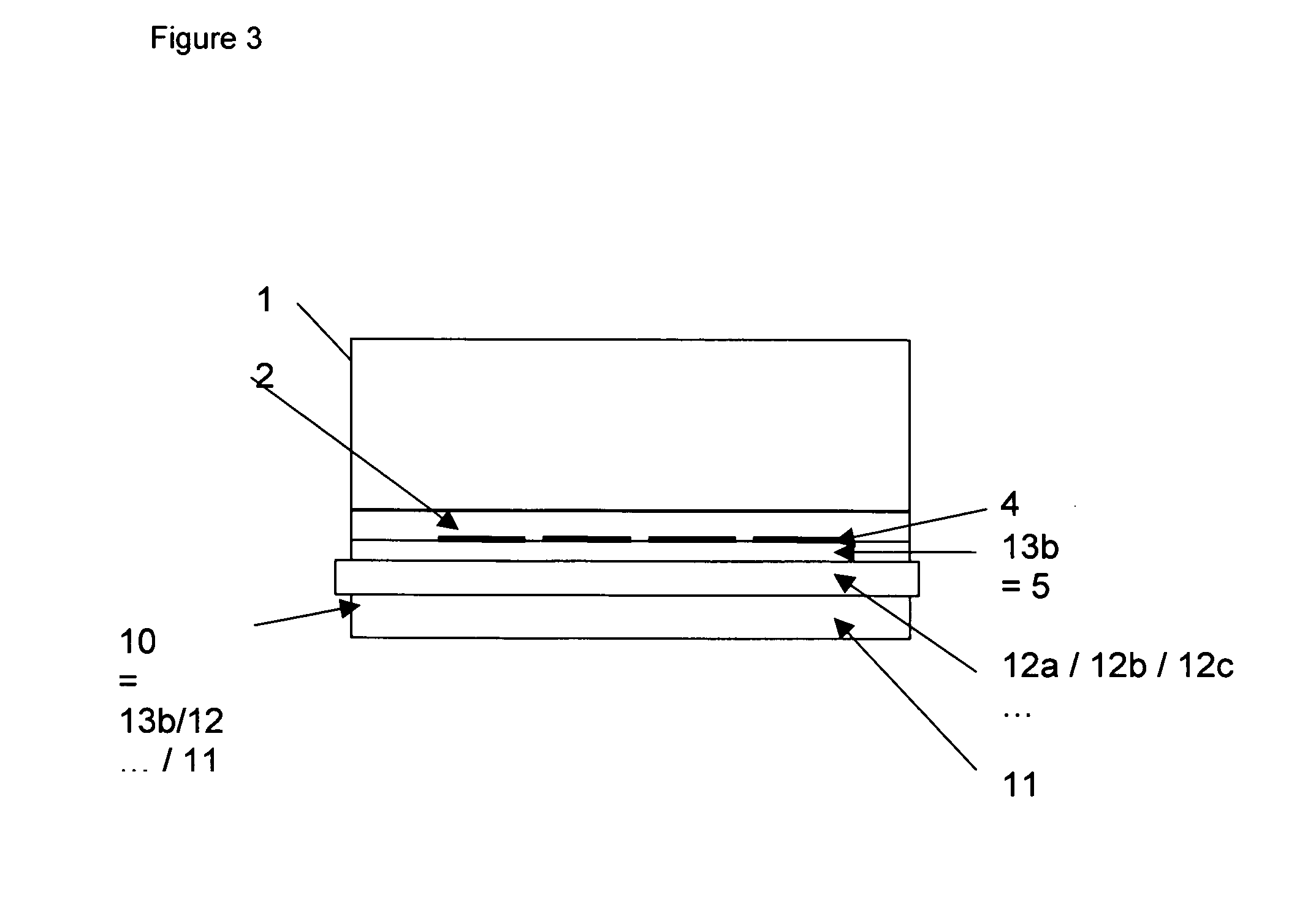
Backsheet with Integrated Adhesive Layer, Functional PO Tie-Layer (13b=5)—FIG. 3
[0206]By coextrusion one produces the following multi-layer film:[0207]Layer one (13b)=20 μm thick layer based on LLDPE-MAH grafted like Orevac 18300 from Arkema, with additives e.g. like Tinuvin NOR 371 FF: 0.8 parts, Chimassorb 81: 0.2 parts, Irgastab FS301: 0.3 parts, possibly with pigments like carbon black or TiO2 (without pigments if the layer flows until above the PV cells).[0208]Layer two (12a)=40 μm thick layer of PE based resin (e.g. Exact 0203 VLDPE from Dexplastomer), with additives e.g. as shown in the previous examples and possibly with pigments.[0209]Layer three (12b)=40 μm thick layer based on a mixture of 25 parts of Random PP copolymer (e.g. Adsyl 5C 30 F from LyondellBasell) and 75 parts of PE (e.g. Exact 0201 VLDPE from Dexplastomer), with additives e.g. as shown in the previous examples and with possibly pigments.[0210]Layer four (12c)=60 μm thick layer based on a mixture of 50 parts...
PUM
| Property | Measurement | Unit |
|---|---|---|
| Fraction | aaaaa | aaaaa |
| Density | aaaaa | aaaaa |
| Particle size | aaaaa | aaaaa |
Abstract
Description
Claims
Application Information