
Sealed cavity and method for producing such a sealed cavity

Active Publication Date: 2012-05-10
COMMISSARIAT A LENERGIE ATOMIQUE ET AUX ENERGIES ALTERNATIVES
View PDF3 Cites 9 Cited by
  • Summary
  • Abstract
  • Description
  • Claims
  • Application Information

AI Technical Summary

Benefits of technology

[0024]In addition, by choosing the height of the release hole or holes, i.e. the distance, along an axis perpendicular to the face of the substrate, between the said face of the substrate and the highest point of the hole or holes located on the side of the face of the cover layer positioned against the sacrificial layer, corresponding to the maximum distance, along an axis perpendicular to the said face of the substrate, between the said face of the substrate and at least one edge of the hole or holes located on the side of one face of the layer, which is positioned against the sacrificial layer, it is possible to choose the desired release speed, i.e. the speed at which the sacrificial layer is eliminated, depending on the technique of plugging of the release hole or holes which is used. The desired height can be obtained, for example, by choosing the angle formed by the lateral flanks, or lateral walls, of the cover layer, the position of the release hole or holes on the lateral flanks of the cover layer, or again the dimensions and / or the shape of the release hole or holes. Thus, it is possible to eliminate the sacrificial layer rapidly by producing one or more holes having sizeable flow areas and / or by producing a large number of holes.
[0026]In addition, unlike the methods of the prior art using channels which are moved out of position relative to the cavity to form entrance-ways to a sacrificial layer, this method allows an effective solid angle for passage of the gases which increases when the elimination of the sacrificial layer starts.
[0033]The cover layer produced in step b) may also cover a portion of the face of the substrate which is not covered by the sacrificial layer and adjacent to the portion of the face of the substrate covered by the sacrificial layer, and the hole produced in step c) may also cross a portion of the cover layer deposited on the portion of the face of the substrate which is not covered by the sacrificial layer. Thus, it is possible to have one or more holes extending as far as the outer portion of the cavity or tangential to this outer portion (and therefore tangential to the face of the substrate), forming peripheral holes at the level of the base of the cover layer in contact with the substrate. In this configuration, when the sacrificial layer is eliminated, the release section therefore increases as this elimination of the sacrificial layer progresses, leading to a reduction of the load losses as the elimination progresses. An elimination of the sacrificial layer through one or more holes formed in this manner is therefore more rapid than an elimination through a hole leading to a channel of constant section before emerging in the cavity, since such a channel implies permanent load losses.
[0037]The hole produced in step c) may include, in a plane of a face of the covering layer, a section of roughly circular or oblong shape. In the case of a section of oblong shape, the length / width ratio of the section (where the length is the dimension parallel to an axis belonging to the said plane of the face of the cover layer such that the distance between this axis and the substrate is roughly constant) may be chosen to be relatively large, i.e. greater than 1 and for example between approximately 1 and 15, so as to create slots, or flow areas, which are sufficiently large to enable the release speed, i.e. the speed of elimination of the sacrificial layer, to be optimised, without increasing the height of the release hole to be plugged relative to the substrate.

Problems solved by technology

In this case, plugging of the release holes by a polymer deposit is incompatible with the production of a low-pressure cavity or cavity under vacuum.
However, this method requires the use of several technological steps.
In addition, the remelting of the alloy under vacuum requires a preparation of this alloy which is complex to implement if it is desired to prevent the presence of aggressive residual gases in the cavity, or gases which are incompatible with the desired pressure.
However, these methods have the disadvantages that they require substantial space, that they make the encapsulation method more complex, and therefore more expensive, and / or that they greatly limit the plugging speed and the possibilities for release of the sacrificial layer.

Method used


Image

  • Sealed cavity and method for producing such a sealed cavity
  • Sealed cavity and method for producing such a sealed cavity
  • Sealed cavity and method for producing such a sealed cavity

Examples


Embodiment Construction

[0047]The present invention will be better understood on reading the description of example embodiments given purely as an indication and in no way restrictively, making reference to the appended illustrations in which:

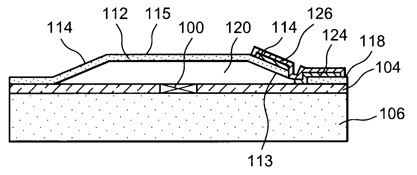
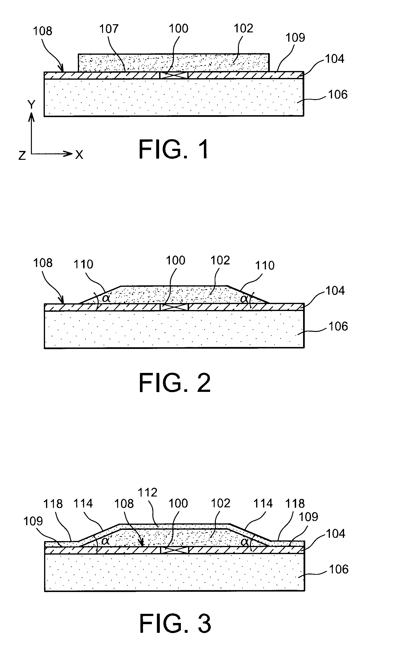
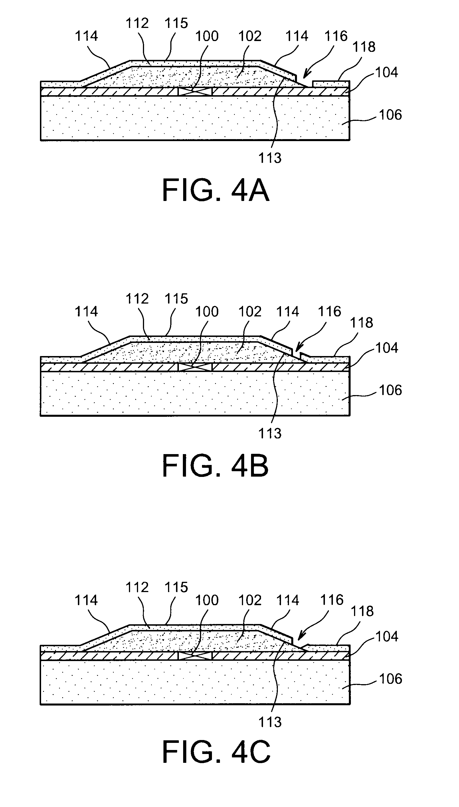
[0048]FIGS. 1 to 9 represent the steps of a method to produce a hermetic cavity, forming the subject of the present invention, according to particular embodiment.

[0049]Identical, similar or equivalent portions of the various figures described below have the same numerical references, to make it easier to move from one figure to another.

[0050]The various parts represented in the figures are not necessarily represented at a uniform scale, in order to make the figures more readable.

[0051]The various possibilities (variants and embodiments) must be understood as not being mutually exclusive, and being able to be combined with one another.

DETAILED ACCOUNT OF PARTICULAR EMBODIMENTS

[0052]Reference is made to FIGS. 1 to 9, which represent steps of a method of production of a ...


PUM


Abstract

A method for producing a sealed cavity, including: a) producing a sacrificial layer on a substrate; b) producing a cover layer covering at least the sacrificial layer and a portion of the face of the substrate not covered by the sacrificial layer, the cover layer including lateral flanks forming, with the substrate, an angle of less than 90°; c) producing a hole through one of the lateral flanks of the cover layer such that a maximum distance between the substrate and an edge of the hole is less than approximately 3 μm, the hole crossing a portion of the cover layer deposited on a portion of the substrate not covered by the sacrificial layer; d) eliminating the sacrificial layer through the hole, forming the cavity; and e) depositing at least one material plugging the hole in a sealed fashion.

Description

TECHNICAL FIELD[0001]The invention concerns the production of a cavity which is sealed against fluids and / or gases, used for example for an encapsulation of a microelectronic device, and more specifically an encapsulation under vacuum in thin layers of devices of the MEMS type (micro-electro-mechanical system) or MEOMS type (micro-electro-optico system), or again of the NEMS type (nano-electro-mechanical system). In the remainder of this document the term “MEMS” will be used to designate a device of the MEMS, NEMS or MEOMS type.[0002]The invention also applies for the production of a cavity forming a channel for circulation of liquid or gaseous fluids.STATE OF THE PRIOR ART[0003]The technique of encapsulation (“packaging”) in thin layers, also called PCM, is perfectly suited for producing an encapsulation of microelectronic devices of the MEMS type, for example sensors, operating at atmospheric pressure. When this type of encapsulation is implemented the MEMS device is covered with ...

Claims


Application Information

Patent Timeline
IPC IPC(8): H01L29/84H01L21/02
CPCB81B2203/0384B81C1/00285B81C2203/0145B81C2203/0136
Inventor PORNIN, JEAN-LOUISJACQUET, FABRICE
Owner COMMISSARIAT A LENERGIE ATOMIQUE ET AUX ENERGIES ALTERNATIVES
Learn More