Infrared optical system

a technology optical system, applied in the field can solve the problems of narrow range of eccentric error, inability of infrared optical system, easy lens formation, etc., and achieve the effect of reducing the length of the entire optical system, reducing the cost of production, and increasing the production cost of the optical system

Inactive Publication Date: 2012-05-10
KK TOPCON
View PDF2 Cites 18 Cited by
  • Summary
  • Abstract
  • Description
  • Claims
  • Application Information

AI Technical Summary

Benefits of technology

[0009]Also, it is necessary to perform precise grinding processing as described above to the above-mentioned existing infrared lens, thus there is a problem that the production cost thereof may increase. It is desired that the infrared lens is produced with low cost.
[0010]Besides, it is necessary that the infrared camera used for the infrared imaging system be compactly contained in the chassis such as a lens barrel or the like, thus the length of the entire optical system should be decreased, and in order to widen the range of clearly imaging, it is necessary to extend the focus as well as to brighten the optical system.
[0011]Therefore, the purpose of the invention, as for an infrared optical system used for the infrared imaging system, is to easily and cheaply produce the infrared optical system which can obtain good image even when used under a severe condition. Also, the purpose of the invention is to provide an infrared optical system, which can be compactly accommodated in the chassis such as a lens barrel by decreasing the length of the entire optical system, and the range of clearly imaging of which can be widened by extending the focus and brightening the optical system.

Problems solved by technology

Regarding the infrared optical system described in the above patent document 1, since the extreme value of the curved surface forming the surface shape of the lens is formed within the range except for the center of the lens and the perimeter of the lens, the range of the eccentric error is narrow and the infrared optical system cannot be made without extremely precise grinding processing.
Due to this reason, the eccentric of lens may easily occur, therefore spherical aberration, distortion, chromatic aberration, or the like may occur.
Thus, there is a problem that it is hard for the existing infrared lens used for the infrared imaging system which is used within a wavelength region of the middle infrared of 3˜5 μm and the far infrared of 8˜12 μm to be used for the particular optical system exposed in the severe environment.
Also, it is necessary to perform precise grinding processing as described above to the above-mentioned existing infrared lens, thus there is a problem that the production cost thereof may increase.

Method used


Image

  • Infrared optical system
  • Infrared optical system
  • Infrared optical system

Examples


first embodiment

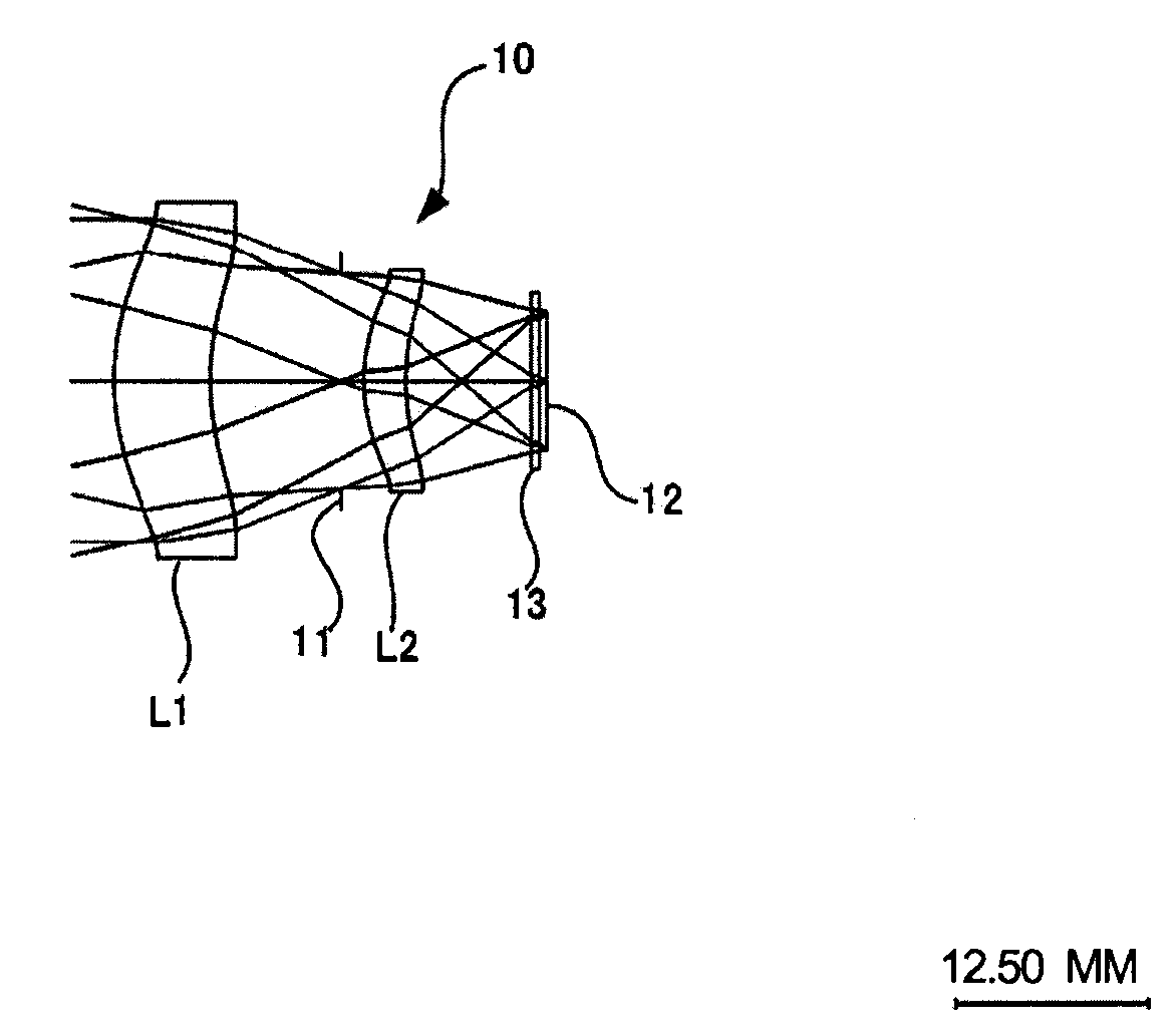
[0039]The embodiment of the infrared optical system 10 will be described below. The infrared optical system 10 is provided with the configuration as illustrated in FIG. 1. Also, the infrared optical system 10 satisfies the condition below, wherein f denotes the focal length of the entire system, and f1 denotes the focal length of the first lens L1.

2.0≦f1 / f . . . condition

[0040]Also, as to the infrared optical system 10, the F number is set to be 0.95, the focus f is set to be 19.7 mm, and the wavelength range is set to be 7 μm˜14 μm (central wavelength is 9.3 μm) though the wavelength range is a wavelength region of the near infrared of 1˜2 μm, the middle infrared of 3˜5 μm and the far infrared of 8˜12 μm. Here, setting the wavelength to be 7 μm˜14 μm is to widen the common wavelength range of far infrared of 8˜12 μm so as to make the imaging within the wide range of the far infrared wavelength region possible.

[0041]Also, as to the infrared optical system 10 according to the first ...

second embodiment

[0056]As to infrared optical system 20 the F number is set to be 0.95, the horizontal visual field standard is set to be f=19.40 mm, the visual angle is set to be 2ω=26°, the focal length of the first lens L1 is set to be f1=120.66 mm. And the numerical aperture NA is set to be 2.5-2.6. Now the following expression is satisfied:

2

0.3

[0057]Also, the first lens L1 and the second lens L2 are produced by molding chalcogenide glass. And, the aperture stop 11, the imaging element 12 and the detector window 13 has the same configuration as the first embodiment.

[0058]The lens data is illustrated as below

surface numberCurvature radius [mm]interval [mm]glass material116.55936.1956chalcogenide glass213.93678.3723321.09562.8044chalcogenide glass491.3894—namewavelength7 μm8 μm10 μm12 μm14 μmchalcogeniderefractive2.60922.60682.60102.59382.5847glassindex

[0059]Also, the aspherical equation Z, the coefficient of the optical path difference function, the optical path difference fu...


PUM


Abstract

An infrared optical system, which can obtain excellent image even when used under a severe condition, is easily and cheaply produced by molding. The infrared optical system, is provided with a configuration of 2 groups 2 lenses having the first lens L1 and the second lens L2 sequentially from the object side, the first lens is a convex aspheric lens of which convex surface protrudes toward the object side, and the second lens is a convex meniscus lens of which convex surface protrudes toward the object side, the infrared optical system is formed by using chalcogenide glass such that the extreme values of the surface shape of the first lens L1 and the second lens L2 are not formed at the lens surface including the outer portion of the lens effective diameter.

Description

CROSS REFERENCE TO RELATED APPLICATION(S)[0001]This application claims the benefit of Japanese Patent Application 2010-251622 filed on Nov. 10, 2010, in the Japanese Patent Office, the entire disclosure of which is incorporated herein by reference for all purposes.TECHNICAL FIELD[0002]The present invention relates to an infrared optical system used within the wavelength region from near infrared to far infrared.BACKGROUND[0003]With reference to the above-described infrared optical system, an infrared lens system with 2 groups 2 lenses and 3 groups 3 lenses formed by Zinc Sulfide (ZnS) has been published (Patent document 1, FIG. 51, FIG. 65, FIG. 79, FIG. 93 and FIG. 96,).[0004]Related Technical Reference[0005]Patent Document[0006][Patent document 1] With reference to Japanese patent publication 2007-241032 which is incorporated herein by reference.SUMMARY[0007]Regarding the infrared optical system described in the above patent document 1, since the extreme value of the curved surfac...

Claims


Application Information

Patent Timeline
Patent Type & Authority Applications(United States)
IPC IPC(8): G02B13/14
CPCG02B13/146G02B5/1814
Inventor TANAMI, YASUNORINAKAMURA, HITOSHITSUBAKI, KOJI
Owner KK TOPCON
Why Eureka
Try Eureka