
Oscillator in which polarity is changed at high speed, magnetic head for mamr and fast data transfer rate HDD

a polarity change, high-speed technology, applied in the direction of data recording, instruments, metal sheet core head, etc., can solve the problems of insufficient magnetization switching velocity for the reference layer, unstable reference layer magnetization, and difficulty in realizing the technology, so as to achieve high information transfer speed, reduce cost, and high reliability

Inactive Publication Date: 2012-05-10
HITACHI LTD
View PDF11 Cites 24 Cited by
  • Summary
  • Abstract
  • Description
  • Claims
  • Application Information

AI Technical Summary

Benefits of technology

[0012]It is an object of the present invention to provide an information recording device suitable for ultrahigh-density and high information transfer speed recording that has high reliability and, as a result, reduces cost by realizing both 1) sufficiently high magnetization switching velocity of the reference layer of the STO and 2) sufficiently stable reference layer magnetization during oscillation of the STO.
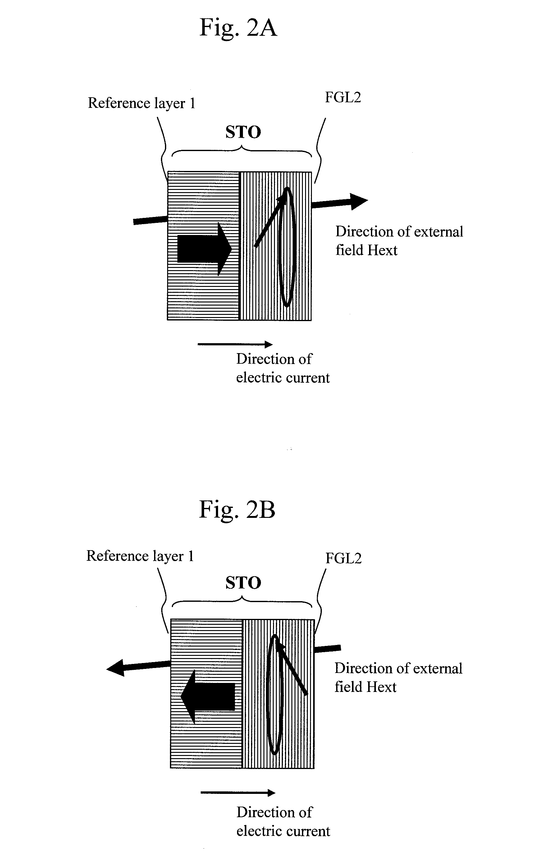
[0036]Slight tilting of a magnetic field applied to the reference layer from a direction perpendicular to the surface of the reference layer is examined (FIG. 12B). During switching, since magnetization and a magnetic field face opposite directions, an effective magnetic anisotropy field Hk-eff substantially decreases according to an increase in a field application angle (Hk-eff-sw) according to the Stoner-Wohlfarth law. On the other hand, during fixing, since magnetization and a magnetic field face substantially the same directions, Hk-eff gently decreases according to a cos side (Hk-eff-osc). For example, when the field application angle is 10 to 20 degrees, it is possible to reduce only a magnetic anisotropy field during switching with little hindrance to a magnetization fixing action of the reference layer. This means that it is possible to increase the velocity factor V while keeping the saturation factor S and the fixing factor F by slightly tilting, from the direction perpendicular to the surface of the reference layer, the magnetic field applied to the reference layer. Alternatively, if Hk is increased not to change the velocity factor V, it is also likely that the fixing factor F can be increased by forty percent.
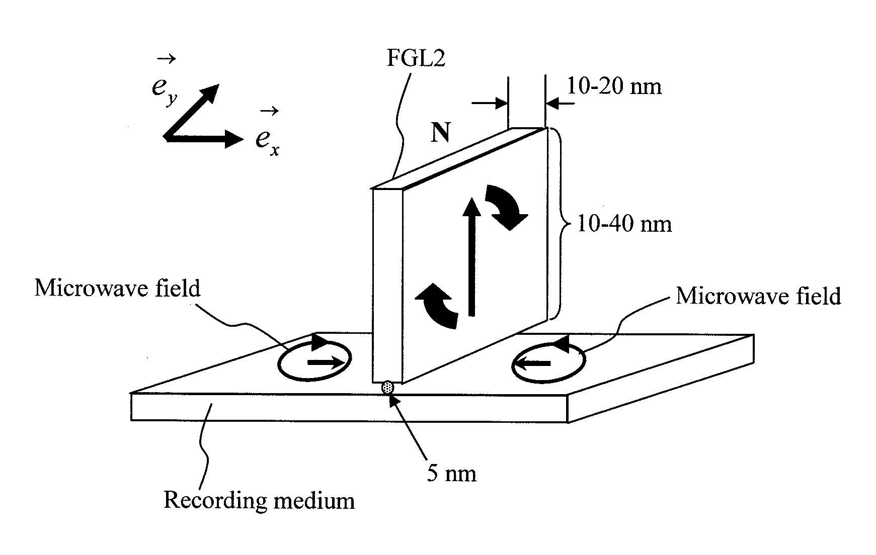
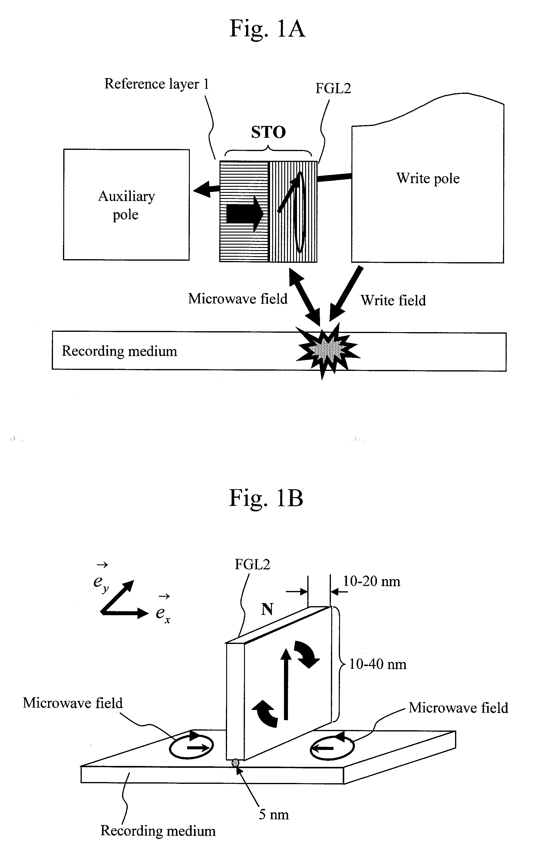
[0039]However, when the magnetic field applied to the FGL tilts from the direction perpendicular to the surface of the reference layer, FGL magnetization tends to be restricted in the direction of the tilt. This is undesirable because oscillation (rotation of the FGL magnetization) is hindered. It is possible to evenly tilt the magnetic field applied to the reference layer by reducing pole width closer to the reference layer compared with pole width closer to the FGL.
[0040]Since magnetization is halfway during switching of the reference layer magnetization, it is likely that unnecessary spin torque is applied to the FGL. The influence of the unnecessary spin torque can be suppressed by temporarily weakening an STO excitation current in synchronization with switching time of write pole polarity. As a result, a stable STO oscillation characteristic can be obtained.
[0043]With the configuration explained above, it is possible to provide a magnetic head and a magnetic recording device suitable for ultra-high density and high information transfer speed recording that have high reliability and, as a result, reduce cost by realizing both of sufficiently high magnetization switching velocity of the reference layer and stabilization of the reference layer magnetization during oscillation of a spin torque oscillator.

Problems solved by technology

Therefore, it is difficult to realize the technology.
Even if a high-Bs material is laminated, sufficient magnetization switching velocity for the reference layer is not obtained.
Since the coercive force of the reference layer is low, when it is attempted to intensify an electric current and supply large spin torque to the FGL, the reference layer magnetization is made unstable by a reaction of the large spin torque.
Therefore, it is difficult to feed a large STO driving current and increase an oscillation frequency.

Method used


Image

  • Oscillator in which polarity is changed at high speed, magnetic head for mamr and fast data transfer rate HDD
  • Oscillator in which polarity is changed at high speed, magnetic head for mamr and fast data transfer rate HDD
  • Oscillator in which polarity is changed at high speed, magnetic head for mamr and fast data transfer rate HDD

Examples


first embodiment

[0087]A specific embodiment of the present invention is explained in detail below with reference to the drawings.

[0088]FIG. 13 shows a sectional structure around a recording mechanism of a recording head and a recording medium taken along a surface perpendicular to the surface of the recording medium (an up down direction in the figure) and parallel to a head running direction (a track direction, which is a left or right direction in the figure). In a recording head 200, a magnetic circuit is configured in an upper part of the figure between a write pole 5 and a faced pole 6. However, it is assumed that the magnetic circuit is generally electrically insulated in the upper part of the figure. In the magnetic circuit, a magnetic line of force forms a closed path. The magnetic circuit does not need to be formed only by a magnet. An auxiliary pole or the like may be arranged on the opposite side of the write pole 5 with respect to the faced pole 6 to form a magnetic circuit. In this cas...

second embodiment

[0094]FIGS. 20A and 20B are diagrams showing a second configuration example of the recording head and the recording medium according to the present invention. FIG. 20A shows a sectional structure around a recording mechanism of the recording head taken along a surface perpendicular to the surface of the recording medium (an up down direction in the figure) and parallel to a head running direction (a track direction, which is a left or right direction in the figure). As in the first embodiment, magnetic circuits are configured in an upper part of the figure between the write pole 5 and the faced pole 6, the magnetic circuits are generally electrically insulated in the upper part of the figure, the recording head includes a coil, a copper wire, and the like for exciting these magnetic circuits, the write pole 5 and the faced pole 6 include electrodes or means for electrically coming into contact with the electrodes and are configured such that an STO driving current can be fed through...

third embodiment

[0098]FIGS. 21A and 21B are diagrams showing a third configuration example of the recording head and the recording medium according to the present invention. In a third embodiment, in the recording head according to the second embodiment, the reference layer 1 is divided and portions of the reference layer 1 are optimized according to functions of the portions. As shown in FIG. 21A, a portion (a high magnetic anisotropy region 10) on the FGL 2 side of the reference layer 1 is desirably more firmly fixed in order to supply spin torque to the FGL 2. On the other hand, the second magnetic flux rectifying layer 13 side of the reference layer 1 is a portion (a magnetization switching start region 9) where a magnetic field distribution from the second magnetic flux rectifying layer 13 is large and magnetization switching of the reference layer 1 is started. Therefore, a switching field is desirably low. In the magnetization switching start region 9, Hk is desirably low. However, excessive...


PUM

PropertyMeasurementUnit
heightaaaaaaaaaa
diameteraaaaaaaaaa
sizeaaaaaaaaaa

Abstract

The present invention provides a magnetic recording head and a magnetic recording device that realize information transfer speed exceeding 1 Gbit / s in microwave assisted magnetic recording applied to a magnetic recording device having recording density exceeding 1 Tbit / in2. Concerning a reference layer that supplies spin torque to a high-speed magnetization rotator serving as a microwave field generation source, when an externally applied field to the reference layer is represented as Hext, a magnetic anisotropy field of the reference layer is represented as Hk, and an effective demagnetizing field in a vertical direction of a film surface of the reference layer is represented as Hd-eff, the fixing layer is configured to satisfy conditions Hext−Hk+Hd-eff>0 and Hext+Hk−Hd-eff>0.

Description

CROSS REFERENCE TO RELATED APPLICATION[0001]U.S. patent application Ser. Nos. 13 / 019,002 and 13 / 208,384 are co-pending applications of this application, the content of which are incorporated herein by cross-reference.CLAIM OF PRIORITY[0002]The present application claims priority from Japanese patent application JP 2010-249270 filed on Nov. 8, 2010, the content of which is hereby incorporated by reference into this application.BACKGROUND OF THE INVENTION[0003]1. Field of the Invention[0004]The present invention relates to a magnetic recording head and a magnetic recording device for irradiating a high-frequency magnetic field on a magnetic recording medium to drive magnetic resonance, inducing magnetization switching of the recording medium, and recording information.[0005]2. Background Art[0006]With the improvement of performance of computers and the increase in speed and the increase in capacity of networks, the amount of information circulated in the form of digital data is dramat...

Claims


Application Information

Patent Timeline
Patent Type & Authority Applications(United States)
IPC IPC(8): G11B5/127G11B21/02
CPCG11B5/3116G11B5/3133G11B2005/0024G11B5/315G11B5/3146
Inventor IGARASHI, MASUKAZUSATO, YOSHIIMOTO, MASATONAGASAKA, KEIICHI
Owner HITACHI LTD
Learn More