
Spatially-fine shear wave dispersion ultrasound vibrometry sampling

a vibrometry and shear wave technology, applied in the field of measuring a shear wave, can solve the problems of relatively low amplitude vibration of sduv, large noise contribution of vibration amplitude, and easy noise of vibration amplitude, so as to reduce noise in preparation

Active Publication Date: 2012-05-10
KONINKLIJKE PHILIPS ELECTRONICS NV
View PDF11 Cites 20 Cited by
  • Summary
  • Abstract
  • Description
  • Claims
  • Application Information

AI Technical Summary

Benefits of technology

[0013]Using a multiline beamformer, as proposed hereinafter allows for finer spatial sampling of the displacement field, and / or spatial sampling in both the elevation and lateral imaging planes (when using 2D arrays vs. conventional 1D arrays). Since more information is extracted from each of the detection pulses, the robustness of the elasticity measures from SDUV is increased. As an added benefit, the total time spent in the procedure can therefore be shortened. This is advantageous from a patient convenience standpoint, and for reducing the potential impact of thermal effects from the repeated delivery of pushes to the excitation point. In addition, the increased pace of radiofrequency (RF) data acquisition makes way for the employment of other shear wave imaging / quantification techniques that require high spatial resolution with high speed.
[0015]As an aspect, from at least one other tracking pulse, the forming is executed so as to overlap resulting receive lines to increase depth of field.
[0028]In a further aspect, a low-pass filter may be used on the measurements, to reduce noise in preparation for the applying.

Problems solved by technology

One main challenge associated with detecting radiation-force-induced shear waves using SDUV is the relatively low amplitude vibration.
The vibration amplitudes are therefore susceptible to noise.
System electronic noise and patient motion such as cardiac or respiratory motion will contribute significant noise to shear wave displacement estimation.
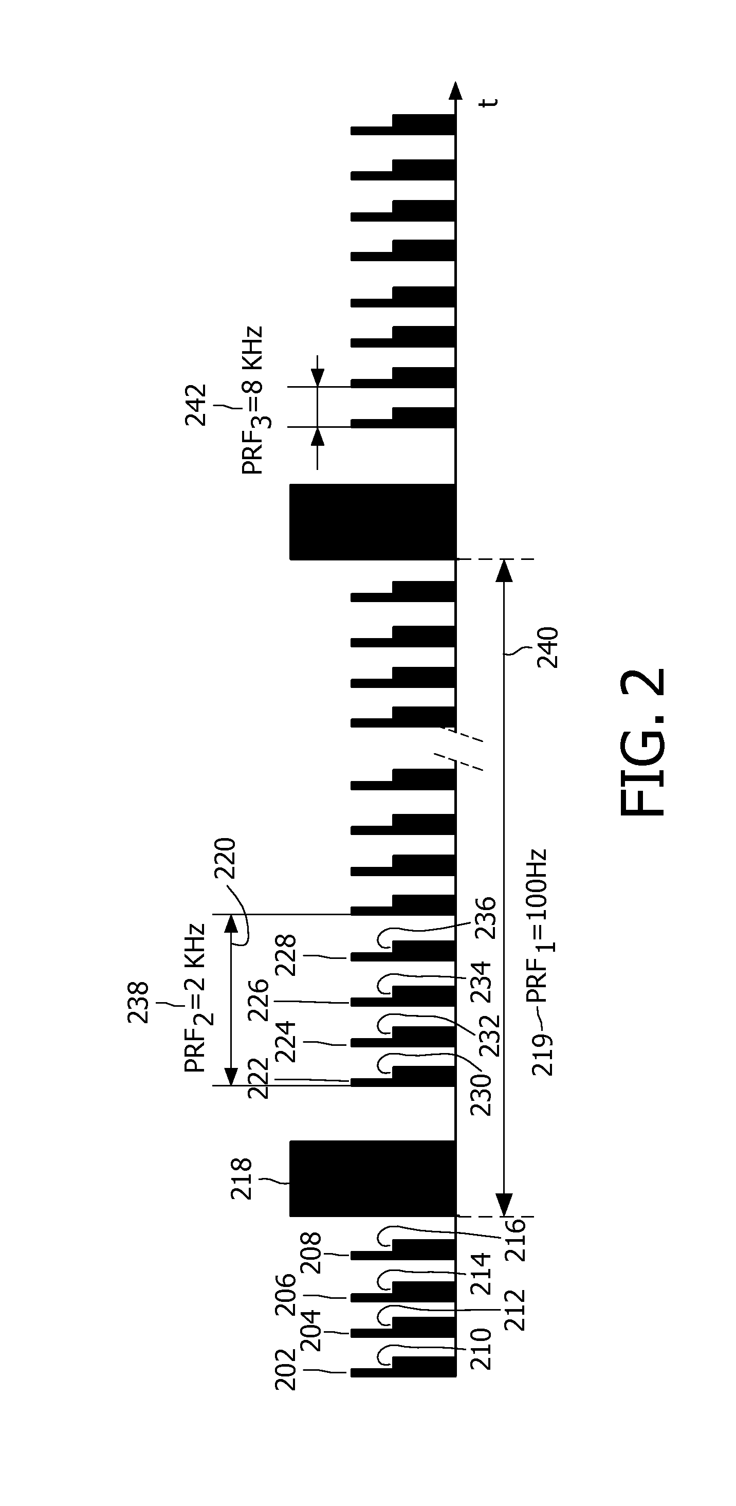
Since the tracking pulse repetition frequency is limited by the speed of sound in tissue and the depth of the ROI, this limits the number of spatial locations that can be sampled, using conventional non-multiline detection sequences.

Method used


Image

  • Spatially-fine shear wave dispersion ultrasound vibrometry sampling
  • Spatially-fine shear wave dispersion ultrasound vibrometry sampling
  • Spatially-fine shear wave dispersion ultrasound vibrometry sampling

Examples


Embodiment Construction

[0040]A general discussion is first had of one version of SDUV with faster sampling. What follows, in this context and starting with FIG. 4, is further exemplary development related to finer spatial sampling.

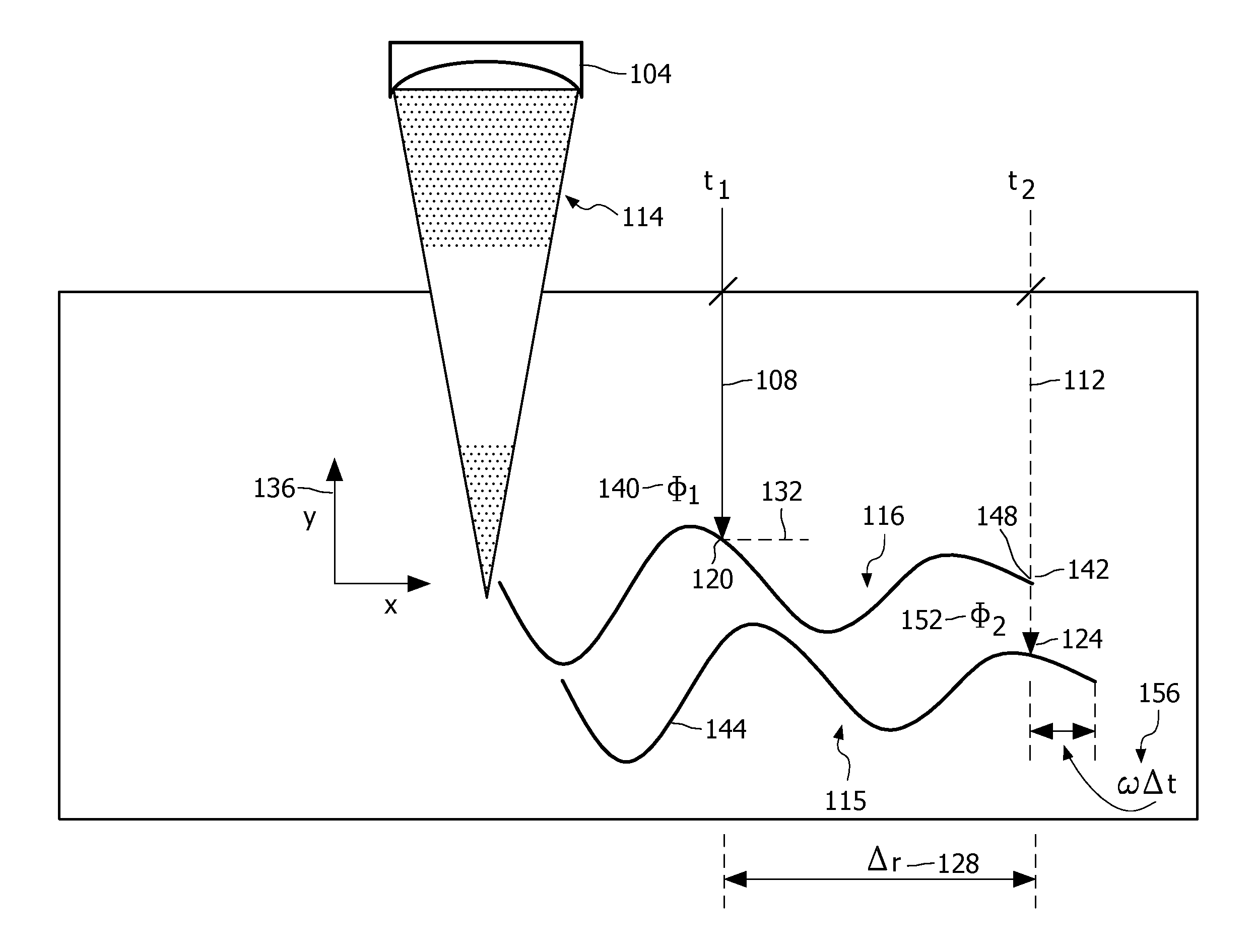
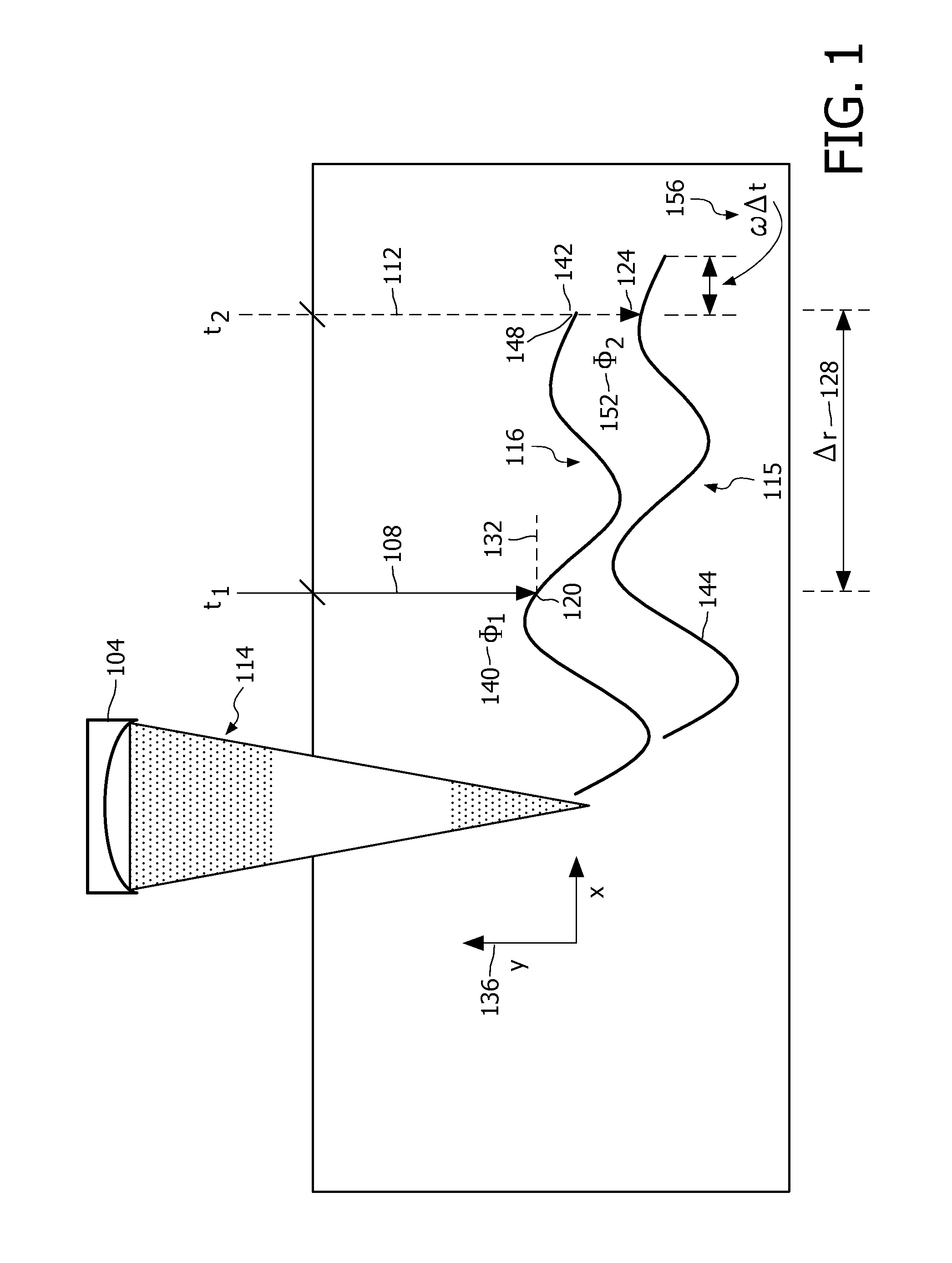
[0041]FIG. 1 depicts, by way of illustrative and non-limitative example, a relation between two consecutive SDUV samples. An ultrasound pushing probe 104 is shown, along with first and second tracking pulses 108, 112 issued at respective sampling times t1, t2, by an ultrasound tracking probe (not shown). The pushing probe 104 sends out a series of focused pushing pulses (or “pushes”) 114 to establish a shear wave 115, a frequency component of which (or “monochromatic shear wave”) is represented by a first trace 116. Tissue vibrates along the y-direction and the shear wave 115 propagates along the x-direction.

[0042]Two separate probes can be used for pushing and tracking respectively. However, this type of bulky configuration is not practical for clinical applications.

[0043]In ad...


PUM


Abstract

Shear wave dispersion ultrasound vibrometry (SDUV) is implemented in some embodiments to form, from a single tracking pulse, in-parallel-directed receive lines (411-426) for making measurements of a monochromatic shear wave. In some embodiments, sampling is performed, over spatial locations by means of passes over the locations, in an interlaced pattern (600) for making measurements of the wave. In some embodiments, measurements are made of the wave and to the measurements are applied a bank of filters (S724) that are tuned to respective candidate wave speeds, all without the need to determine a difference between wave phases at different spatial locations (451-454).

Description

FIELD OF THE INVENTION[0001]The present invention is directed to measuring a shear wave and, more particularly, to doing so by Shear Wave Dispersion Ultrasound Vibrometry (SDUV).BACKGROUND OF THE INVENTION[0002]Mechanical changes in living tissue correlate with pathological changes. As between healthy and pathological tissue, the shear elastic modulus (stiffness) and viscosity can vary significantly. With the advent of ultrasound elasticity imaging development over the past decade, many clinical studies have shown that tissue visco-elastic properties provide useful information to physicians for better cancer diagnosis and therapy assessment.[0003]Shear Wave Dispersion Ultrasound Vibrometry (SDUV) is an acoustic radiation force based technique that measures tissue shear elasticity and viscosity by characterizing shear wave speed dispersion, i.e., by frequency. An application of this technique is the non-invasive measurement of liver stiffness to stage liver fibrosis and cirrhosis.[00...

Claims


Application Information

Patent Timeline
IPC IPC(8): A61B8/00
CPCA61B5/0048G01S7/52042A61B8/485A61B8/00G01S7/52085
Inventor BURCHER, MICHAEL R.XIE, HUAFERNANDEZ, ANNA TERESAROBERT, JEAN-LUC
Owner KONINKLIJKE PHILIPS ELECTRONICS NV
Learn More