

Ferromagnetic Material Sputtering Target
a technology of ferromagnetic material and target, which is applied in the direction of vacuum evaporation coating, electrolysis components, coatings, etc., can solve the problems of unstable discharge, low magnetic flux, and insufficient method, so as to improve the characteristics of magnetic recording medium, increase the target density, and reduce the surface area
Active Publication Date: 2012-05-17
JX NIPPON MINING& METALS CORP
View PDF3 Cites 21 Cited by
- Summary
- Abstract
- Description
- Claims
- Application Information
AI Technical Summary
Benefits of technology
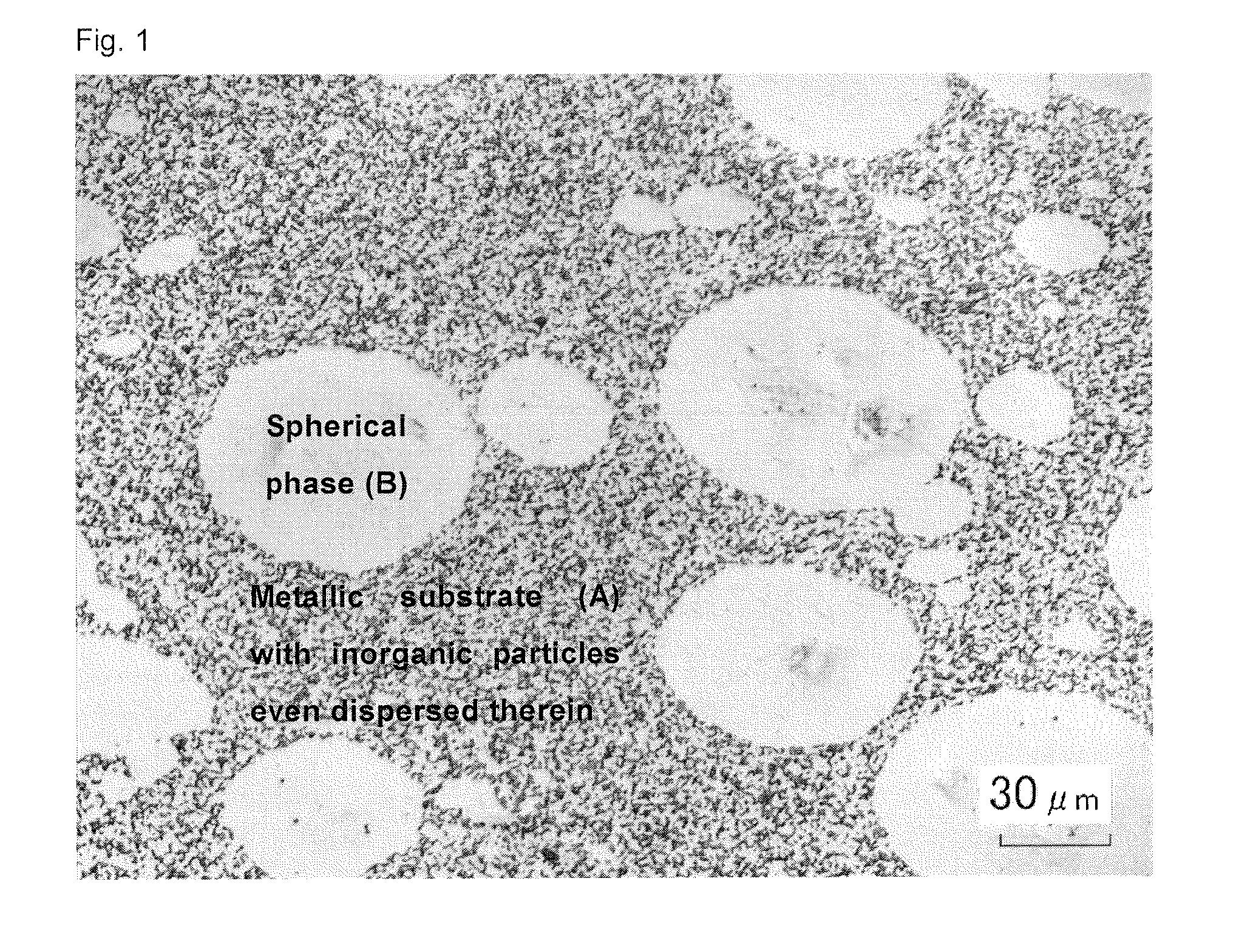
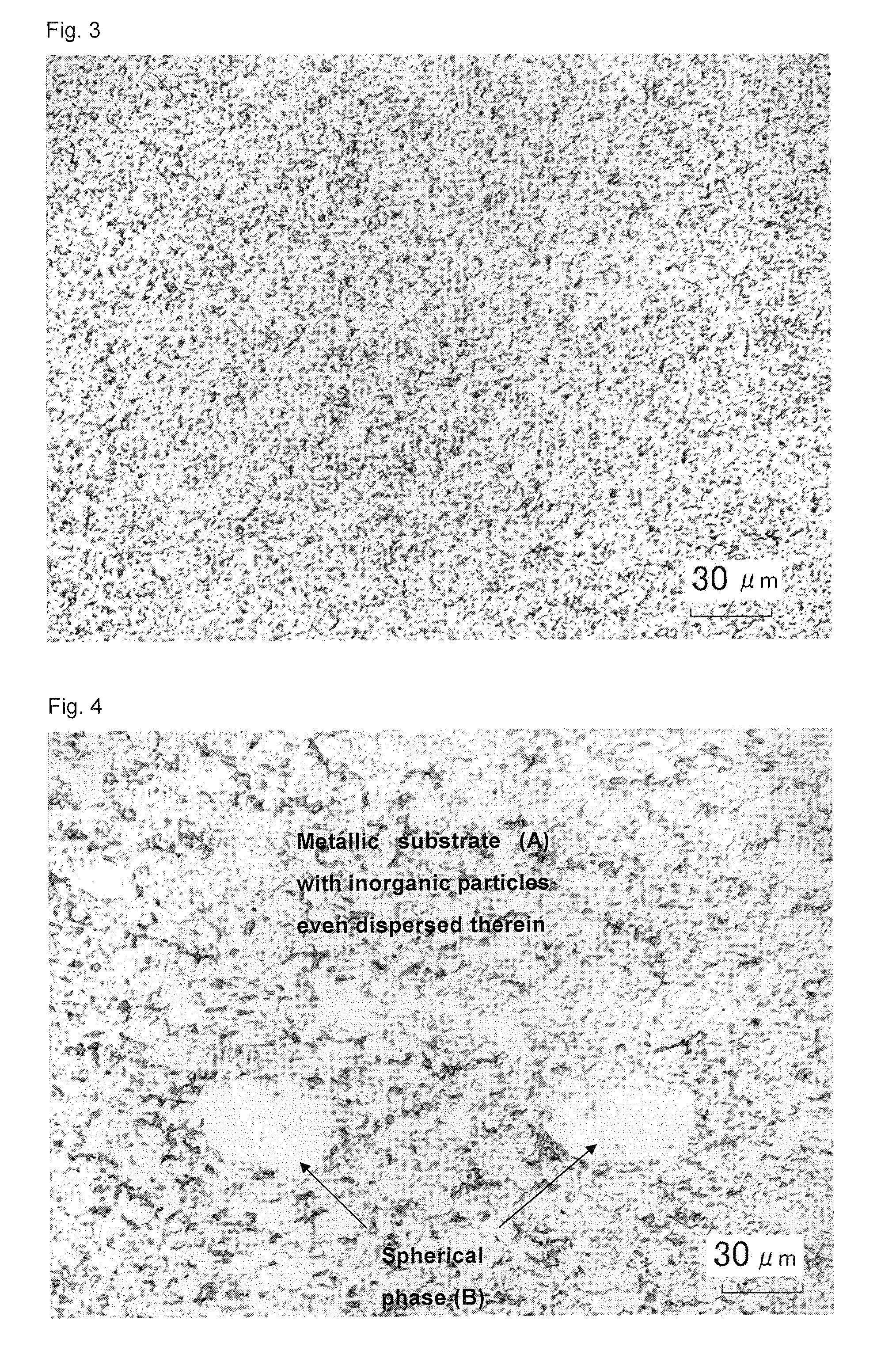
[0037]In the present invention, it is also effective to contain 0.5 mol % or more and 10 mol % or less of one or more elements selected from B, Ti, V, Mn, Zr, Nb, Ru, Mo, Ta, and W as additive elements. These are elements which are added as needed in order to improve the characteristics as a magnetic recording medium. Desirably, the phase (B) has a diameter of 30 to 150 μm and is of a spherical shape. A spherical shape is able to increase the target density since pores are not formed easily at the interface of the metallic substrate (A) and the phase (B) upon manufacturing the target material with the sintering meth
Problems solved by technology
Generally, if a magnetron sputtering device is used to sputter a ferromagnetic material sputtering target, since much of the magnetic flux from the magnet will pass through the target, which is a ferromagnetic body, the leakage magnetic flux will decrease, and there is a major problem in that a discharge does not occur during the sputtering or, even if a discharge doe
Method used
View moreImage
Smart ImageViewing Examples

Examples
 PUM
| Property | Measurement | Unit |
|---|---|---|
| Fraction | aaaaa | aaaaa |
| Fraction | aaaaa | aaaaa |
| Diameter | aaaaa | aaaaa |
Abstract
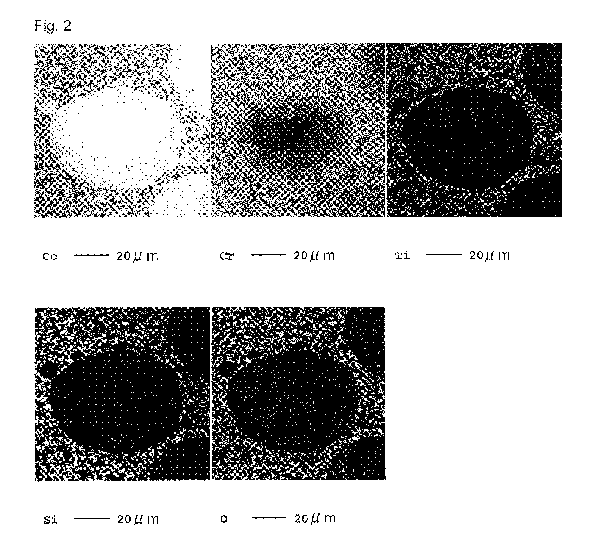
A ferromagnetic material sputtering target made of metal having a composition containing 20 mol % or less of Cr, and Co as the remainder thereof, wherein the structure of the target includes a metallic substrate (A), and, in the metallic substrate (A), a spherical phase (B) containing 90 wt % or more of Co in which the difference between the longest diameter and the shortest diameter is 0 to 50%. Provided is a ferromagnetic material sputtering target capable of improving the leakage magnetic flux to obtain a stable electrical discharge with a magnetron sputtering device.
Description
TECHNICAL FIELD[0001]The present invention relates to a ferromagnetic material sputtering target for use in the deposition of a magnetic thin film of a magnetic recording medium, and particularly of a magnetic recording layer of a hard disk adopting the perpendicular magnetic recording system, and to a sputtering target which is able to obtain stable electrical discharge when sputtered with a magnetron sputtering device.BACKGROUND ART[0002]In the field of magnetic recording as represented with hard disk drives, a material based on Co, Fe or Ni as ferromagnetic metals is used as the material of the magnetic thin film which is used for the recording. For example, Co—Cr-based or[0003]Co—Cr—Pt-based ferromagnetic alloys with Co as its main component are used for the recording layer of hard disks adopting the longitudinal magnetic recording system.[0004]Moreover, composite materials of Co—Cr—Pt-based ferromagnetic alloys with Co as its main component and nonmagnetic inorganic matter ar...
Claims
Login to View More Application Information
Patent Timeline
 IPC IPC(8): C23C14/14C23C14/34
CPCC22C1/0433H01F41/183C23C14/3414C22C19/07
InventorSATO, ATSUSHIARAKAWA, ATSUTOSHI
OwnerJX NIPPON MINING& METALS CORP