Oscillation circuit having negative resistance element and oscillator using the oscillation circuit

a negative resistance element and oscillator technology, applied in the direction of oscillator, pulse generator, pulse technique, etc., can solve the problem that the oscillation frequency, such as the oscillation characteristic, cannot be stabilized during direct modulation, and achieve the effect of speeding up the apparatus

Inactive Publication Date: 2012-05-17
CANON KK
View PDF2 Cites 32 Cited by
  • Summary
  • Abstract
  • Description
  • Claims
  • Application Information

AI Technical Summary

Benefits of technology

[0008]In order to apply these oscillators to communication or imaging in a terahertz band, the modulation operation of oscillation output is necessary. Methods of output modulation include direct modulation in which a bias applied to a negative resistance element is switched as in a conventional semiconductor laser, and external modulation in which a mechanical chopper or an optical component is externally provided. Of these methods, direct modulation is promising from the viewpoint of downsizing and speeding up an apparatus. On the other hand, an os...

Problems solved by technology

Accordingly, the oscillator using a negative resistance element has the possibility that the oscillation charact...

Method used


Image

  • Oscillation circuit having negative resistance element and oscillator using the oscillation circuit
  • Oscillation circuit having negative resistance element and oscillator using the oscillation circuit
  • Oscillation circuit having negative resistance element and oscillator using the oscillation circuit

Examples


examples

[0040]Now, an oscillation circuit according to the present embodiment will be described using FIGS. 3A to 5. FIG. 3A is an external view of the present embodiment and FIG. 3B is a cross-sectional view thereof. FIGS. 4A, 4B and 5 are drawings used to describe modifications of the present embodiment.

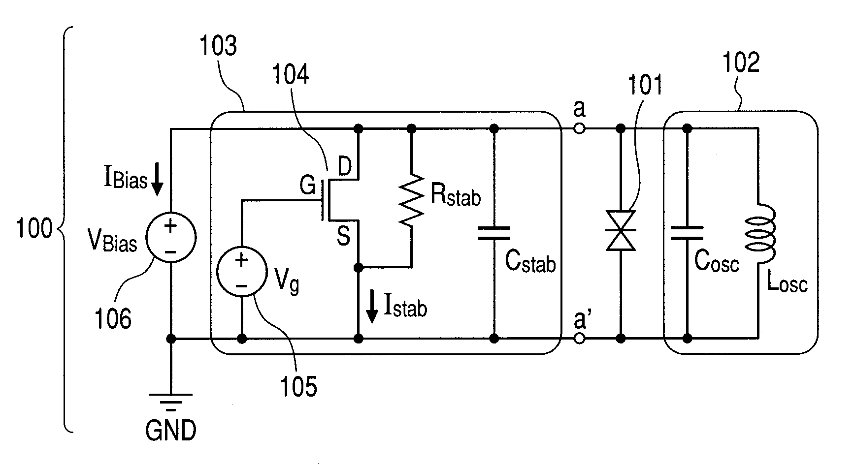
[0041]An oscillation circuit 200 of the present embodiment is formed on a substrate 230, and is comprised mainly of an RTD 201, a patch antenna 202, a FET 204, an adjusting device 205, an MIM (Metal-Insulator-Metal) structure 209, and a resistive element 210. The RTD 201 uses a triple-barrier quantum well structure including the following constituent elements:

First barrier layerAlAs1.3 nmFirst quantum well layerInGaAs7.6 nmSecond barrier layerInAlAs2.6 nmSecond quantum well layerInGaAs5.6 nmThird barrier layerAlAs1.3 nm

[0042]Here, the first quantum well layer, the second barrier layer and the second quantum well layer are layers of InGaAs / InAlAs lattice-matched to InP having a plane orient...


PUM


Abstract

An oscillation circuit including: a negative resistance element; a resonance circuit connected to the negative resistance element; and a stabilization circuit connected in parallel with the negative resistance element to suppress parasitic oscillation, wherein the stabilization circuit includes a variable shunt resistor and a adjusting device for adjusting the shunt resistor.

Description

TECHNICAL FIELD [0001]The present invention relates to an oscillation circuit having a negative resistance element used to generate electromagnetic waves and to an oscillator using the oscillation circuit. More particularly, the invention relates to an oscillation circuit using a negative resistance element, such as a resonant tunneling diode, to generate electromagnetic waves containing a frequency component in a terahertz-band frequency domain (frequencies of 30 GHz or higher but not higher than 30 THz) in at least part of the waves, and an oscillator using the oscillation circuit.BACKGROUND ART [0002]As a solid-state device which operates and oscillates in a frequency band of terahertz waves, an oscillator using a negative resistance element, such as a resonant tunneling diode (RTD), has been proposed. In particular, an oscillator using an RTD takes advantage of an electromagnetic wave gain based on the intersubband transition of electrons in the semiconductor quantum well struct...

Claims


Application Information

Patent Timeline
IPC IPC(8): H03B7/08H03B7/06H03B7/00
CPCH03B7/08
Inventor KOYAMA, YASUSHISEKIGUCHI, RYOTA
Owner CANON KK
Why Eureka
Try Eureka