Single enclosure surround sound loudspeaker system and method

a loudspeaker system and single enclosure technology, applied in the field of sound reproduction, can solve the problems of compromising home décor, affecting the sound quality of the system, and affecting the quality of the sound, so as to reduce the chance of producing unsatisfactory surround sound effects, easy to install, and easy to switch

Active Publication Date: 2012-05-17
POLK AUDIO LLC
View PDF6 Cites 40 Cited by
  • Summary
  • Abstract
  • Description
  • Claims
  • Application Information

AI Technical Summary

Benefits of technology

[0015]The single enclosure multi-surround channel loudspeaker system of the present invention generates audio outputs which, when reflected from room walls or surfaces and perceived by a listener, creates a sonic illusion of phantom sound sources, simulating the sound that would be heard from conventional separate, elevated surround loudspeakers, each reproducing a unique surround channel's program material. The enclosure of the invention may be placed at various locations in the room behind the listener; for example, on the listening room's floor, on a table or on a high shelf, and the switchable sound magnitude shaping produces corresponding elevated phantom sound sources that generate a surround sound effect that is perceived by a listener at the listening position in the room. The single enclosure multi-surround channel loudspeaker system of the present invention is easy to install, since it is wireless and its output can be easily switched to match its location, thereby reducing the chances of producing unsatisfactory surround sound effe

Problems solved by technology

Installing and wiring conventional multiple-speaker surround channel systems, which are typically far removed from the associated multichannel audio processor and power amplifier often integrated into a home theater receiver, involves significant effort on the part of the consumer and may severely compromise home décor.
Such adaptive systems represent an awkward compromise, however, because the optimum location for a lamp fixture to enable it to provide good lighting effects very likely will not match the optimum location for a surround system speaker, which must be configured for effective

Method used


Image

  • Single enclosure surround sound loudspeaker system and method
  • Single enclosure surround sound loudspeaker system and method
  • Single enclosure surround sound loudspeaker system and method

Examples


Embodiment Construction

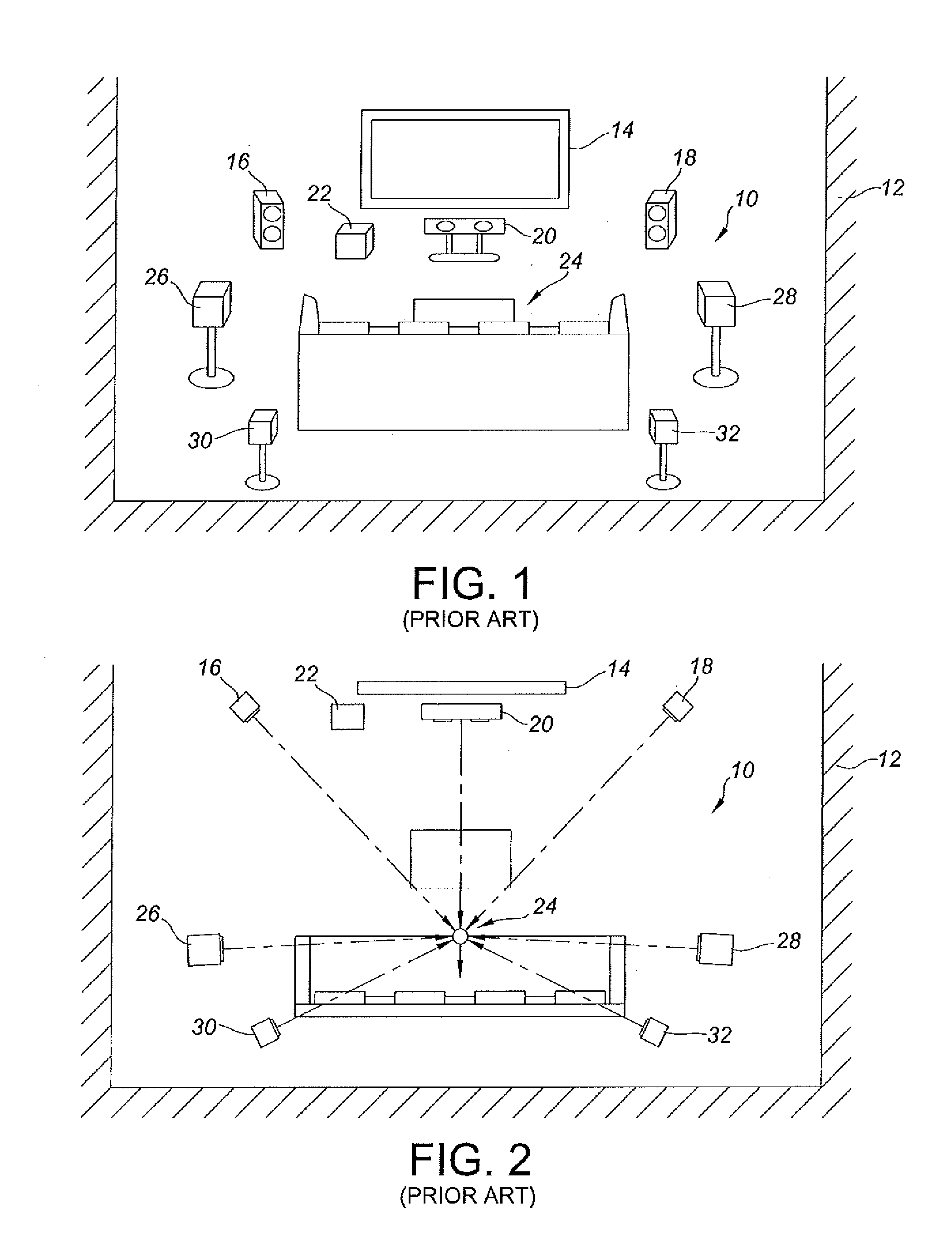
[0042]Turning now to a more detailed consideration of the present invention, FIGS. 1 and 2 are perspective and top plan views of a typical prior art surround sound system, as generally indicated at 10, located in a media space, or room 12. The illustrated system is a conventional Dolby® digital set-up having a home theater or other audio / video (AV) source 14, left channel speakers 16, right channel speakers 18, and center channel speakers 20, and a subwoofer 22, located in front of a primary seating area for listeners at a listening station 24 such as a sofa or chairs or the like. The system includes a pair of left and right surround speakers 26 and 28 spaced from the sides of the listening station to provide a sense of spaciousness to sound radiated by the speakers, and providing ambient sounds for AV programs such as movies and concerts. Also included in the system 10 are left and right back speakers 30 and 32 located generally behind and to the sides of the listening station to p...


PUM


Abstract

A single enclosure loudspeaker system projects multi-channel surround sound into a listener's room, and so replaces multiple conventional surround channel loudspeakers. The loudspeaker system includes a pair of opposing multi transducer arrays oriented laterally toward walls or reflecting surfaces (relative to the viewing axis) within the media space. The multi-element arrays are housed in a single self-powered loudspeaker enclosure along with a single (or multiple) low-frequency electro-acoustical drive element(s). In one embodiment of the invention, surround channel program material is pre-processed by an integrated wireless transmission device that performs certain digital signal processing and channel mixing steps in advance of wireless surround signal broadcast to a receiver.

Description

[0001]This application claims priority benefit of U.S. Provisional Application No. 61 / 413,206, filed Nov. 12, 2010, and entitled, “Single Enclosure Surround Sound Loudspeaker System and Method”, the disclosure of which is hereby incorporated herein in its entirety.BACKGROUND OF THE INVENTION[0002]1. Field of the Invention[0003]The present invention relates in general to the reproduction of sound and more specifically to the application of acoustic and psycho-acoustic principles in the design of a loudspeaker system for use in multi-channel systems generically known as “surround-sound” systems which typically include a plurality of loudspeakers arrayed beside and behind the listeners.[0004]2. Discussion of the Prior Art[0005]Traditional home-theater installations configured to provide “surround sound” require the use or installation of multiple loudspeakers, typically incorporating at least two surround channel loudspeakers placed laterally and behind the home-theater seating area in...

Claims


Application Information

Patent Timeline
IPC IPC(8): H04R5/02H04R5/00
CPCH04R5/02H04R5/04H04R2205/022H04R2420/07H04R29/008H04S3/008H04R2201/028H04S2420/01
Inventor STAROBIN, BRADLEY M.
Owner POLK AUDIO LLC
Why Eureka
Try Eureka