Thermal gasification reactor for producing heat energy from waste

a technology of waste heat energy and gasification reactor, which is applied in the direction of gasification process details, combustion process, combustible gas production, etc., can solve the problems of landfills, environmental protection solutions, and requiring space in landfills, and achieve the effect of destroying waste and meliorating the aforementioned disadvantages

Active Publication Date: 2012-05-17
GREEN ENERGY & TECH
View PDF9 Cites 15 Cited by
  • Summary
  • Abstract
  • Description
  • Claims
  • Application Information

AI Technical Summary

Benefits of technology

[0007]The present invention seeks to ameliorate the aforementioned disadvantages by providing an apparatus that is able to destroy waste in a safe and controlled environment.

Problems solved by technology

However, landfills require space, and that is something many countries have less and less of, particularly in and adjacent to urban areas, which areas generate the greatest volume of waste material.
Landfills, if unsecure, are also not an environmentally friendly solution.
Waste organic materials may decompose and yield harmful products capable of contaminating the soil and ground water.
Any fire in such tyre dumps are extremely difficult to extinguish, and emit huge amounts of pollution.
However, both of these processes have been found to have too many operational problems to be commercially viable.
The problems include difficulties with the separation and removal of particulate matter and residual solids and, referring particularly to the apparatus in U.S. Pat. No. 5,085,738, difficulties in maintaining an oxygen free atmosphere over the molten metal bath while continually feeding the organic solids therein.
Other known methods have other kinds of drawbacks, such as producing pollutants during the disposal process, not being able to process inorganic waste along with the organic fraction of the waste, or do not produce enough energy even to support the waste disposal process.

Method used


Image

  • Thermal gasification reactor for producing heat energy from waste
  • Thermal gasification reactor for producing heat energy from waste
  • Thermal gasification reactor for producing heat energy from waste

Examples


Embodiment Construction

[0017]It should be noted that the following detailed description is directed to a thermal reactor for producing heat energy by destroying waste and is not limited to any particular size or configuration but in fact a multitude of sizes and configurations within the general scope of the following description.

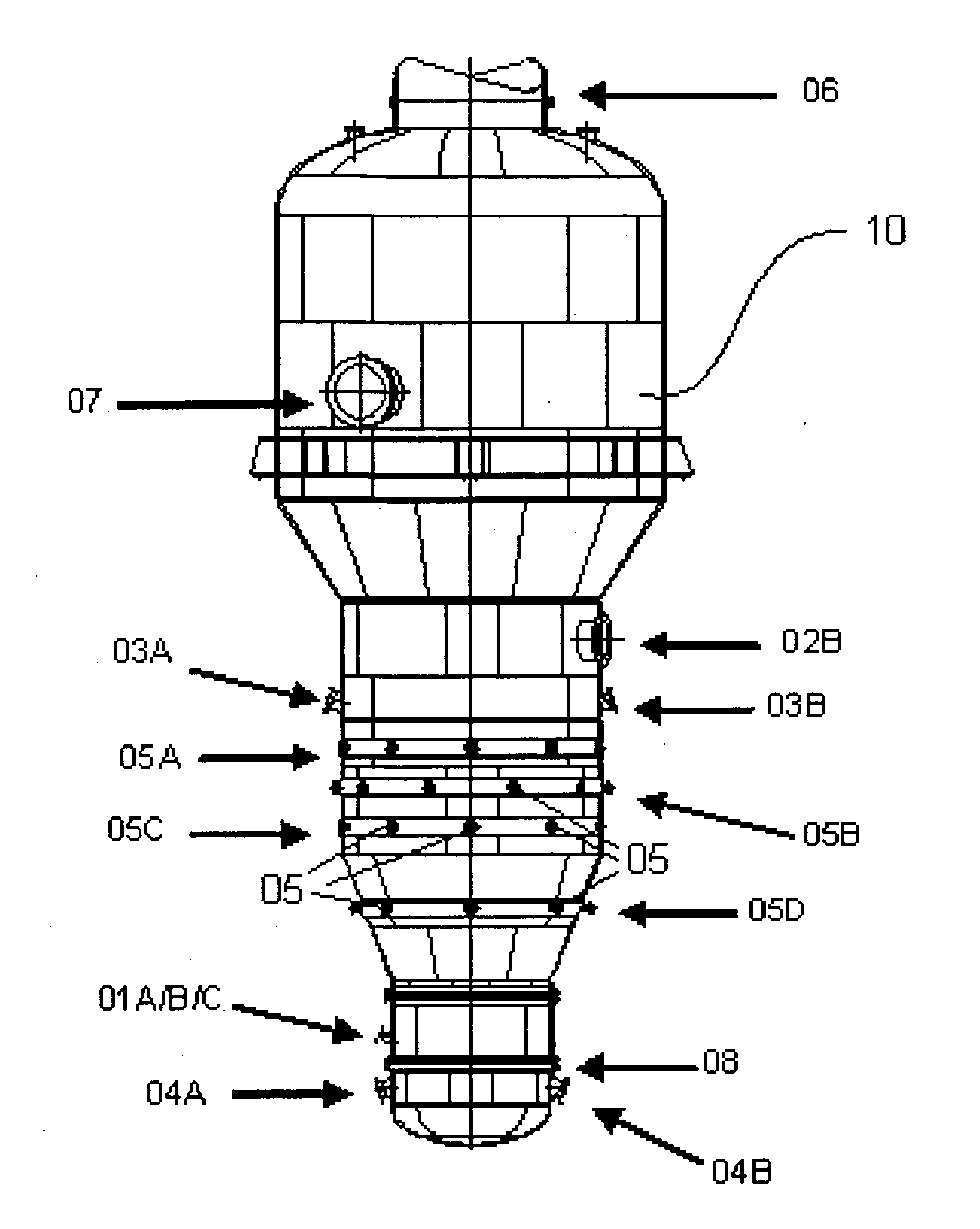
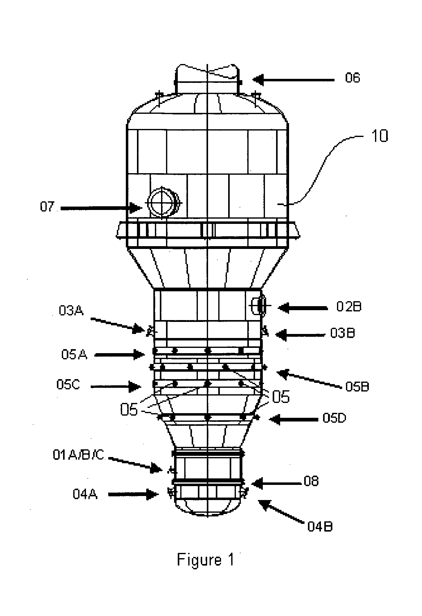
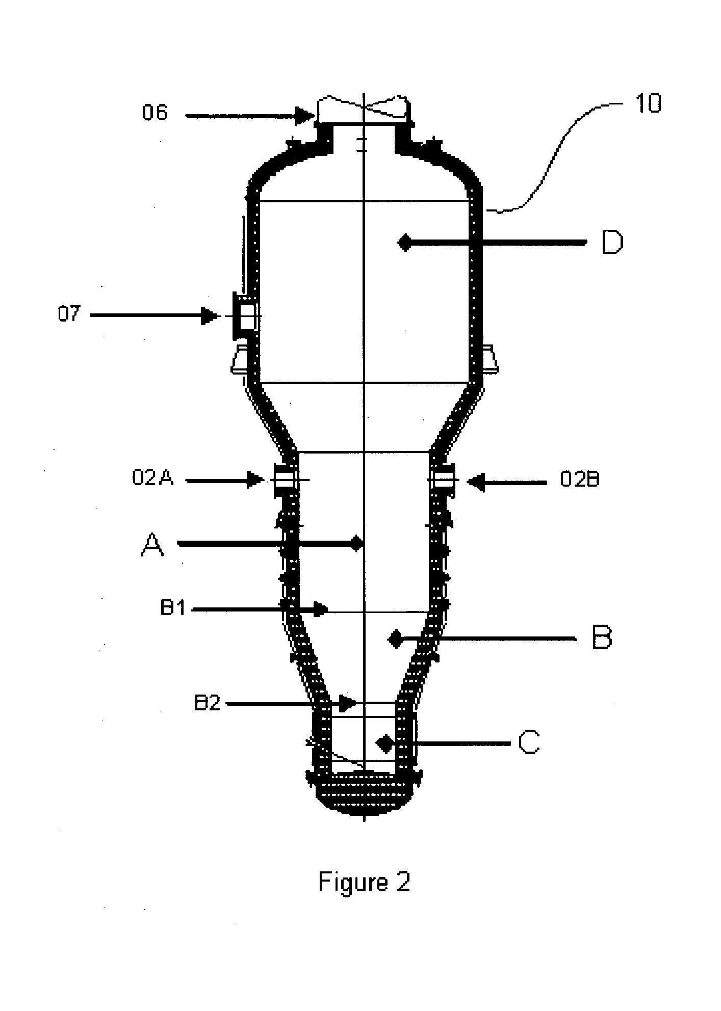
[0018]Referring to FIG. 1 and FIG. 2, there is shown a thermal reactor which converts organic and / or inorganic waste to useful products in the form of synthesis gas and inert glass-like mineral aggregate, respectively, both of which are re-cycled as useable products. The reactor includes an elongated vessel (10) having an internal volume, said internal volume comprising an oxidizing zone (C) located at a lower portion of the internal volume, a carbon bed (B) located above the oxidizing zone (C), a gasification zone (A) located above the carbon bed (B), and a gas retention zone (D) located above the gasification zone (A). A carbon bed is located below the gasification zone (A). Th...


PUM


Abstract

A thermal reactor for producing usable heat energy by destroying waste including a vessel wherein organic waste upon entering said vessel gasifies as it falls onto a carbon bed and is transformed into a synthesis gas with high heat and kinetic energy that can be harnessed to produce electricity. Inorganic waste upon entering melts as it falls onto the carbon bed and exits via slag ports to form an inert slag. Because there is no oxygen present in the gasification zone, the waste is not combusted and neither furan or dioxin are formed. The waste includes either prepared refuse derived fuel (RDF) or unprepared raw waste or a combination thereof.

Description

FIELD OF INVENTION[0001]The present invention relates to a thermal reactor for the generation of heat energy and other recyclable by-products by the destruction of organic and inorganic waste.BACKGROUND OF INVENTION[0002]The need for efficient and environmentally sound methods of waste disposal is ever more urgent. Landfills have been used extensively for waste disposal, since landfill usage typically requires only the collection and transport of the waste to the site. However, landfills require space, and that is something many countries have less and less of, particularly in and adjacent to urban areas, which areas generate the greatest volume of waste material. Landfills, if unsecure, are also not an environmentally friendly solution.[0003]Waste organic materials may decompose and yield harmful products capable of contaminating the soil and ground water. Other organic wastes (such as vehicle tyres and plastic products) exhibit little or no decomposition in a landfill. At present,...

Claims


Application Information

Patent Timeline
Patent Type & Authority Applications(United States)
IPC IPC(8): B09B3/00
CPCF23G5/0276Y02E20/16F23G5/46F23G7/003F23G7/12F23G2202/20F23G2203/403F23G2206/203F23G2207/30F23G2207/60F23G2209/281Y02E20/12C10J3/08C10J3/20C10J2300/0943C10J2300/0946C10J2300/0996C10J2300/1238F01D13/00F01D15/10F23G5/027F23G5/033F23G5/04F23J15/02F23G5/085Y02P20/129Y02E20/18Y02E50/10Y02E50/30
Inventor ALI, MAZLANMOHD SHARIFF, SITI FATIMAHWEBB, CHRISTOPHER JOHN
Owner GREEN ENERGY & TECH
Why Eureka
Try Eureka