Secondary battery temperature-increasing control apparatus, vehicle including the same, and secondary battery temperature-increasing control method

Active Publication Date: 2012-05-17
TOYOTA JIDOSHA KK
View PDF0 Cites 17 Cited by
  • Summary
  • Abstract
  • Description
  • Claims
  • Application Information

AI Technical Summary

Benefits of technology

[0008]The invention provides a secondary battery temperature-increasing control apparatus capable of efficiently increasing the temperature of a secondary battery with the use of

Problems solved by technology

In the above publication, however, neither the efficiency in increasing the temperature of the battery nor the state of the secondary battery after the tempe

Method used


Image

  • Secondary battery temperature-increasing control apparatus, vehicle including the same, and secondary battery temperature-increasing control method
  • Secondary battery temperature-increasing control apparatus, vehicle including the same, and secondary battery temperature-increasing control method
  • Secondary battery temperature-increasing control apparatus, vehicle including the same, and secondary battery temperature-increasing control method

Examples


Example

First Embodiment

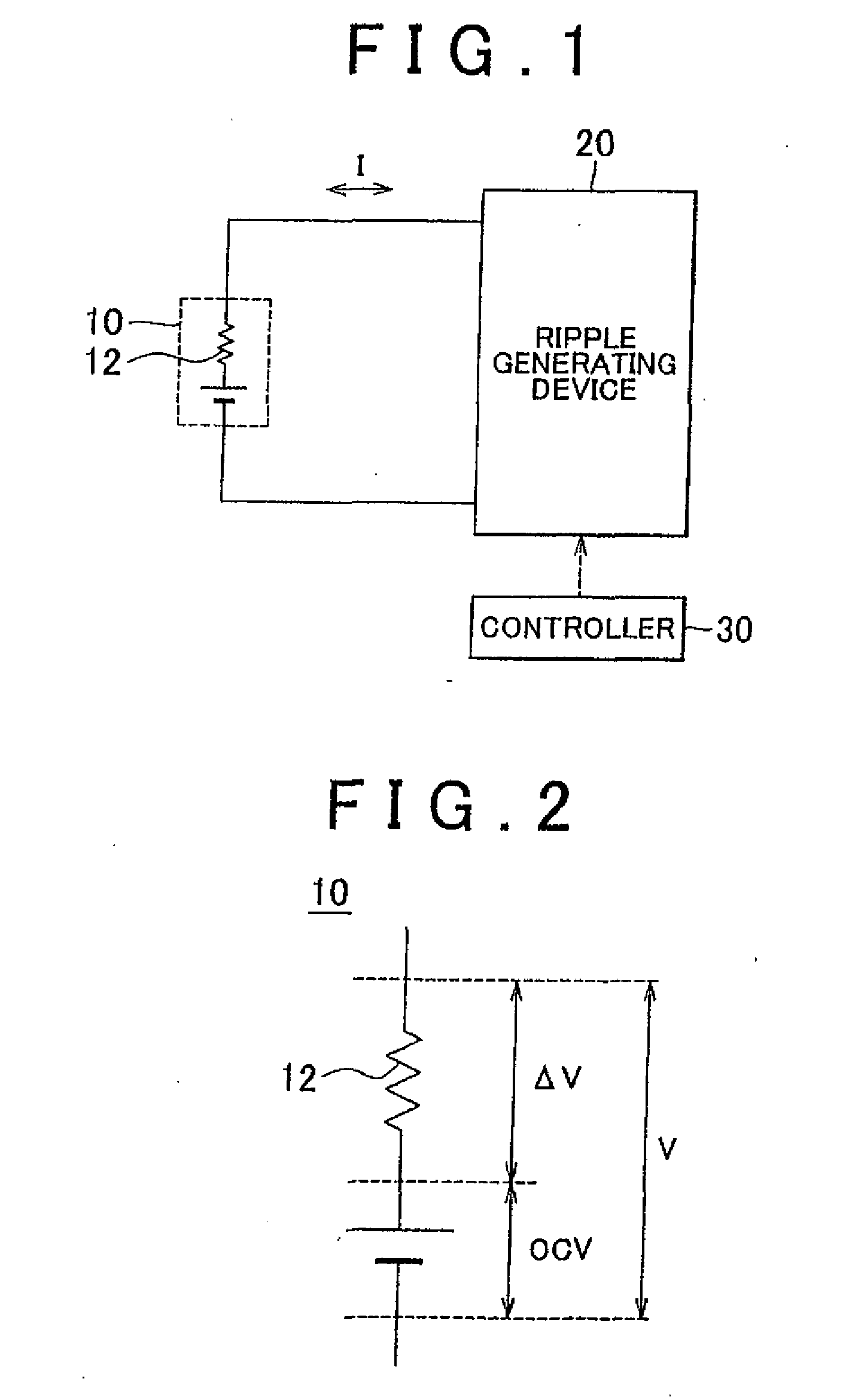
[0049]FIG. 1 is a diagram for explaining a secondary battery temperature-increasing method of the invention. Referring to FIG. 1, the system includes a secondary battery 10, a ripple generating device 20, and a controller 30. The ripple generating device 20 is connected to the secondary battery 10.

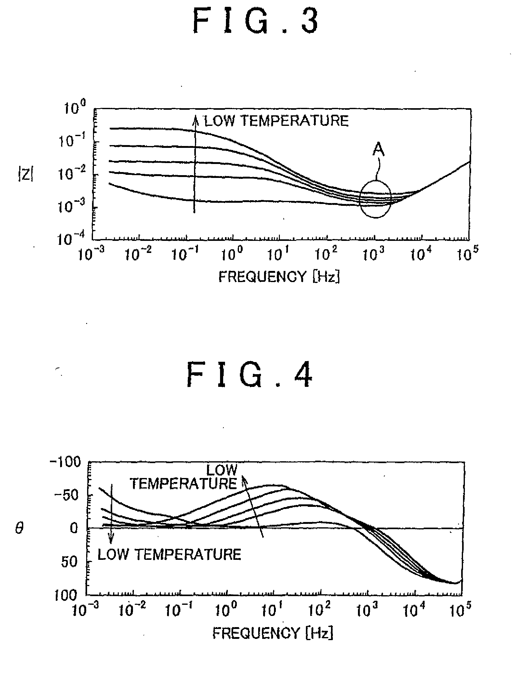
[0050]The secondary battery 10 is a rechargeable battery, typified by a lithium ion battery or a nickel-hydrogen battery. The secondary battery 10 has an internal resistance 12. The internal resistance 12 has a temperature dependence and significantly varies depending also on the frequency of the electric current that flows in the battery as described later.

[0051]The ripple generating device 20 is controlled by the controller 30 and causes a ripple current I at a predetermined frequency to flow in the secondary battery 10. Thus, in the invention, a ripple current is caused to flow in the secondary battery to increase the temperature of the secondary battery from the inside ...

Example

Second Embodiment

[0108]In the second embodiment, a ripple frequency is selected, at which the allowable output power WoutB of the secondary battery 10 achieved when the ripple temperature increase operation is performed becomes maximum.

[0109]An overall configuration of a hybrid vehicle, in which a secondary battery temperature-increasing control apparatus according to the second embodiment is used, is the same as that of the hybrid vehicle 100 shown in FIG. 7.

[0110]FIG. 13 is a functional block diagram of part of the ECU 70A of the second embodiment, the part relating to the control of the boost converter 22. Referring to FIG. 13, the ECU 70A further includes a frequency range setting section 126 and a frequency selecting section 128 in addition to the components of the ECU 70 shown in FIG. 11. In addition, the ECU 70A includes a second calculating section 120A and a carrier generating section 124A instead of the second calculating section 120 and the carrier generating section 124....

Example

Third Embodiment

[0133]In the second embodiment and the modification thereof, the ripple frequency is selected so that the allowable output power Wont of the secondary battery 10 achieved when the ripple temperature increase operation is performed becomes maximum. In a third embodiment, however, the frequency, at which it is ensured that the electric power required to start the engine 60 (FIG. 7) with the motor generator 56 (FIG. 7) is obtained, is selected as the ripple frequency. When the allowable output power WoutB corresponding to the selected ripple frequency is equal to or higher than the allowable output power WoutA, it is determined to perform the ripple temperature increase operation and, when the allowable output power WoutB is lower than the allowable output power WoutA, it is determined not to perform the ripple temperature increase operation.

[0134]FIG. 17 is a diagram showing the relation between the electric power required to start the engine and the temperature of the...


PUM


Abstract

A first calculating section (118) calculates an allowable output power (WoutA) of the secondary battery before a ripple temperature increase operation for increasing the temperature of a secondary battery by causing a ripple current to flow in the secondary battery is performed, the allowable output power being determined in advance based on the temperature and a state of charge (SOC) of the secondary battery. A second calculating section (120) calculates the allowable output power (WoutB) achieved when the ripple temperature increase operation is performed. A determining section (122) determines whether to perform the ripple temperature increase operation so that when the allowable output power (WoutB) is equal to or greater than the allowable output power (WoutA), the ripple temperature increase operation is performed and, when the allowable output power (WoutB) is smaller than the allowable output power (WoutA), the ripple temperature increase operation is not performed.

Description

BACKGROUND OF THE INVENTION[0001]1. Field of the Invention[0002]The invention relates to a secondary battery temperature-increasing control apparatus, a vehicle including the same, and a secondary battery temperature-increasing control method. In particular, the invention relates to a technology for performing temperature increasing control to increase the temperature of the secondary battery with the use of the heat generation caused by the internal resistance of the secondary battery.[0003]2. Description of the Related Art[0004]In general, in secondary batteries, typified by lithium-ion batteries and nickel-hydrogen batteries, charging and discharging characteristics are degraded as the temperature decreases. When the temperature of the battery is low, it is required to quickly increase the temperature of the battery.[0005]Japanese Patent Application Publication No. H11-26032 (JP-A-11-26032) describes an apparatus for healing up a battery for an electric vehicle. In this apparatus...

Claims


Application Information

Patent Timeline
IPC IPC(8): B60L11/18H02J7/00H01M10/48B60L50/16G01R31/36H01M10/60H01M10/615H01M10/625H01M10/633H01M10/6571
CPCB60L11/1872B60L11/1875B60L2240/526Y02T10/705B60L2260/56Y02T10/7005Y02T10/7011B60L2240/545B60L58/25B60L58/27H01M10/637H01M10/625Y02T10/70
Inventor TAKAHASHII, HIDENORINISHI, YUJITAZAWA, MASATOSHIMATSUSAKA, MASANOBU
Owner TOYOTA JIDOSHA KK
Why Eureka
Try Eureka