Load driver with constant current variable structure

a constant current variable and driver technology, applied in the direction of oscillator generators, pulse techniques, electronic switching, etc., can solve the problems of increasing current consumption in the driver circuit, power element damage, increasing current consumption, etc., and achieve the effect of reducing the consumption amount of constant current and electric current supplied to the clamp circui

Active Publication Date: 2012-05-24
DENSO CORP
View PDF5 Cites 49 Cited by
  • Summary
  • Abstract
  • Description
  • Claims
  • Application Information

AI Technical Summary

Benefits of technology

[0020]According to a second aspect, a load driver includes a power element, a river circuit, a clamp circuit. The power element is connected to a load. The power element is provided by a semiconductor switching element, and has a driving terminal. The driver circuit supplies a constant current to the driving terminal to drive the power element. The clamp circuit is connected to the driving terminal and clamps a voltage applied to the driving terminal on a predetermined voltage when the voltage reaches the predetermined voltage by the constant current supplied from the driver circuit. The driver circuit includes a variable constant current circuit that reduces a value of the constant current after the voltage reaches the predetermined voltage to a value smaller than that of the constant current supplied before the voltage reaches the predetermined voltage,
[0021]In such a structure, after the voltage of the driving terminal of the power element reaches the predetermined voltage, the value of the constant current supplied to the driving terminal is reduced by the variable constant current circuit. Therefore, the electric current supplied to the clamp circuit is reduced. Accordingly, the consumption amount of the constant current is reduced.

Problems solved by technology

However, the increase in the value I of the constant current results in an increase in current consumption in the driver circuit.
In such a structure, if an overshoot occurs when the gate of the power element reaches a fully on state, the power element will be damaged.
As a result, the current consumption will be increased.

Method used


Image

  • Load driver with constant current variable structure
  • Load driver with constant current variable structure
  • Load driver with constant current variable structure

Examples


sixth embodiment

[0140]A sixth embodiment will be described with reference to FIGS. 8 through 10. Hereinafter, a structure different from those of the first through fifth embodiments will be mainly described.

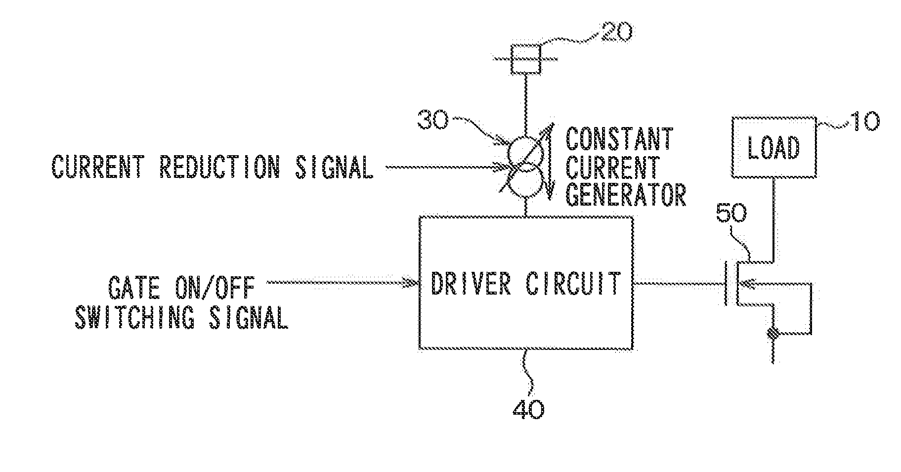
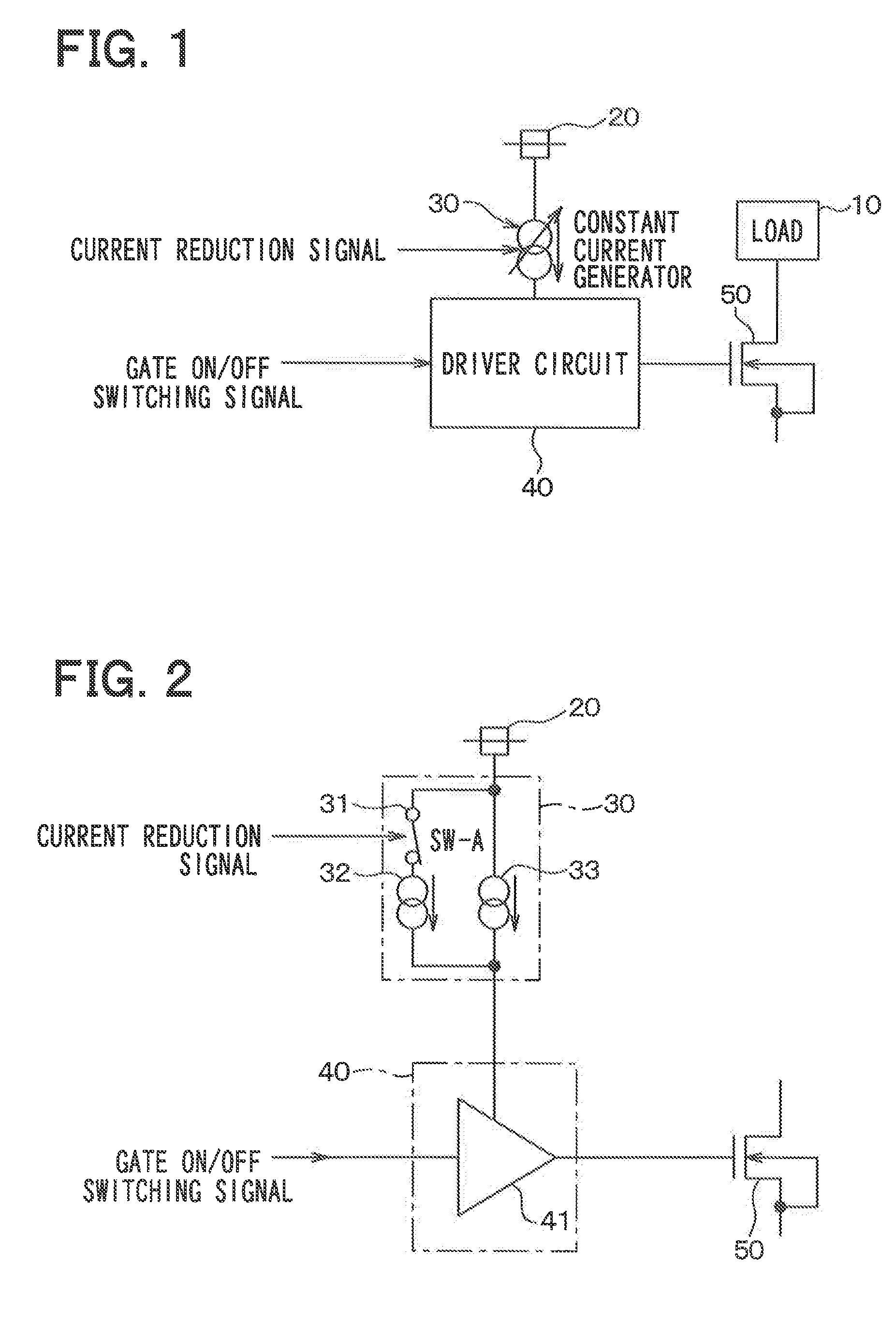
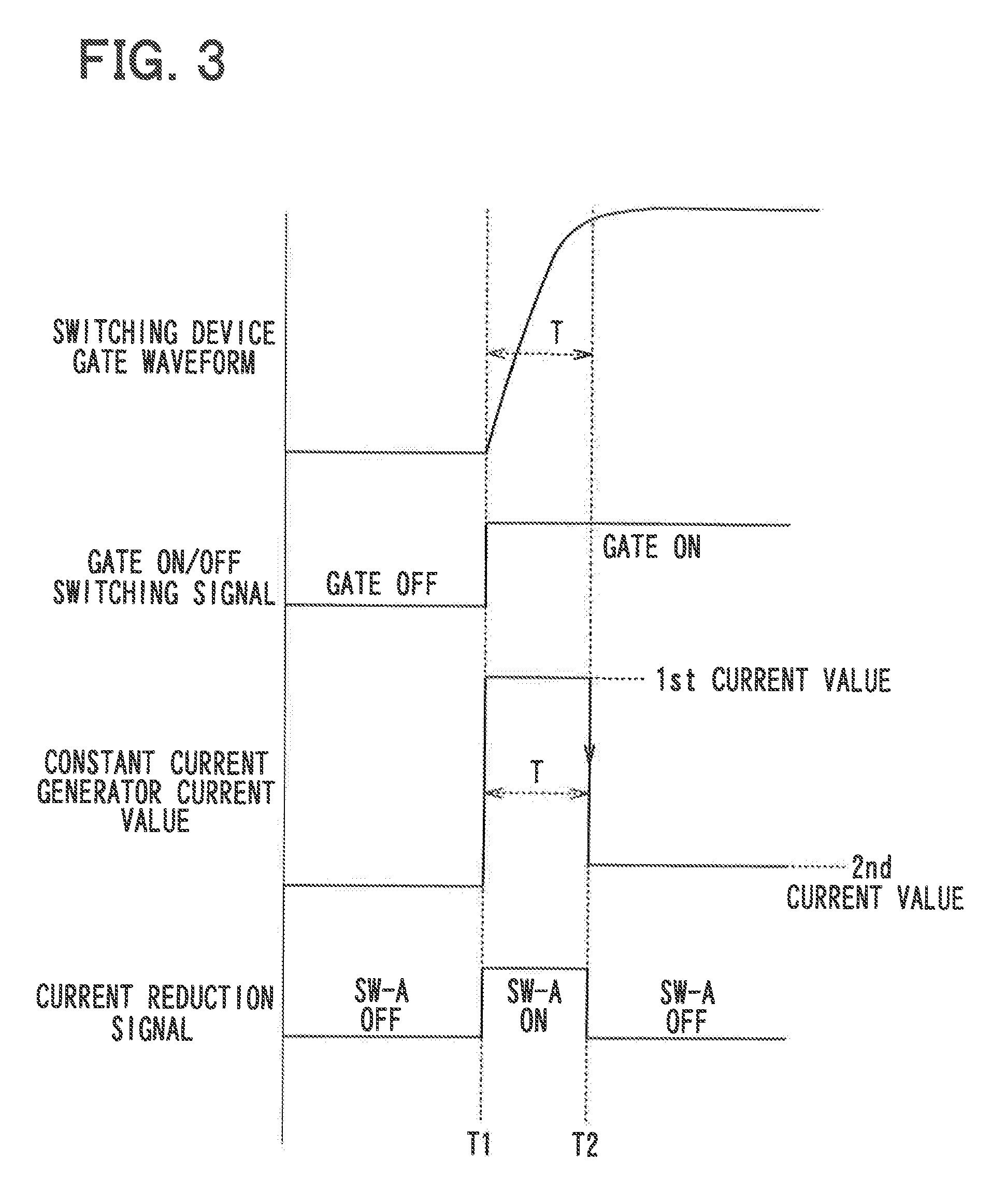
[0141]In the above described embodiments, the current reduction signal is inputted into the constant current generator 30 from the external device at a predetermined timing, based on the rising time of the gate of the switching element 50 or the power element 10. Alternatively, the load driver can additionally have a circuit that generates the current reduction signal utilizing a timing to input the switching signal. In such a case, accuracy of the rising time, that is, the timing to control the value of the constant current can be improved by monitoring the gate voltage of the switching element 50 and the power element 10.

[0142]Hereinafter, a structure of the circuit that generates the current reduction signal will be described. FIG. 8 is a schematic view illustrating the load driver according ...

seventh embodiment

[0157]A seventh embodiment will be described with reference to FIGS. 11 through 13. Hereinafter, a structure different from that of the sixth embodiment will be mainly described. In the present embodiment, the current reduction control circuit 70 measures a timer period from a timing where the switching signal to turn on the switching element 50 is begun to be inputted into the driver circuit 40 to a timing where the driver circuit 40 drives the switching element 50 while the switching signal is being inputted into the driver circuit 40. The current reduction control circuit 70 outputs the current reduction signal when the timer period has elapsed.

[0158]FIG. 11 is a circuit diagram of the load driver according to the present embodiment. As shown in FIG. 11, the current reduction control circuit 70 includes an inverter 74, a delay circuit 75, and an AND circuit 73.

[0159]The inverter 74 is an inverting element that inverts the switching signal IN and inputs the inverted switching sign...

eighth embodiment

[0171]An eighth embodiment will be described with reference to FIG. 14. Hereinafter, a structure different from that of the sixth embodiment will be mainly described. FIG. 14 is a schematic diagram of a load driver according to the eighth embodiment. As shown in FIG. 14, the power element 10 can be employed as the load 10, and the current reduction control circuit 70 can be added to the pre-driver unit 60. Also, the switching element 50 is a P-channel MOSFET, for example.

[0172]It is to be noted that an on state of the power element 10 means a conducted state, and an off state of the power element 10 means a non-conducted state. This can be applied to the other embodiments.

[0173]In a case where the power element 10 is employed as the load 10, a voltage is applied to the gate of the power element 10 by turning off the switching element 50 through the driver circuit 40, and the constant current supplied to the driver circuit 40 is reduced after the power element 10 becomes the on state...


PUM


Abstract

A load driver includes a switching element connected to a load, a constant current generator that generates a constant current, and a driver circuit that turns on the switching element for an on-period, which depends on a value of the constant current and is shortened with an increase in the value of the constant current. The constant current generator supplies a first constant current having a first current value to the driver circuit during the on-period, and supplies a second constant current having a second current value smaller than the first current value after the on-period has elapsed and the switching element reaches an on state.

Description

CROSS REFERENCE TO RELATED APPLICATION[0001]This application is based on Japanese Patent Applications No. 2010-260397 filed on Nov. 22, 2010, No. 2010-260400 filed on Nov. 22, 2010, No. 2011-91848 filed on Apr. 18, 2011 and No. 2011-66218 filed on Mar. 24, 2011, the disclosure of which are incorporated herein by reference.FIELD OF THE INVENTION[0002]The present invention relates to a load driver with a constant current variable structure,BACKGROUND OF THE INVENTION[0003]For example, JP2009-71956A, corresponding to US2009 / 0066402A1, describes a gate drive circuit for driving a power switching element, such as an insulated gate bipolar transistor (IGBT), as a load. The described gate drive circuit has a first turn-on power supply circuit for turning on a power switching element. The first turn-on power supply circuit has a first turn-on power source as a power source dedicated for the first turn-on power supply circuit.[0004]The first turn-on power supply circuit supplies a voltage eq...

Claims


Application Information

Patent Timeline
Patent Type & Authority Applications(United States)
IPC IPC(8): H03K3/00
CPCH03K17/163H03K3/012H03K17/168H03K17/166
Inventor KAWAMOTO, TEPPEISENDA, YASUTAKAMIURA, RYOTARO
Owner DENSO CORP
Why Eureka
Try Eureka