Multi-spectral imaging

a multi-spectral imaging and imaging technology, applied in the field of multi-spectral imaging, can solve the problems of reduced reliability, increased cost, increased complexity, etc., and achieve the effects of improving spatial and spectral resolution, improving temporal performance, and high temporal resolution

Active Publication Date: 2012-05-24
KONINKLIJKE PHILIPS ELECTRONICS NV
View PDF4 Cites 21 Cited by
  • Summary
  • Abstract
  • Description
  • Claims
  • Application Information

AI Technical Summary

Benefits of technology

[0019]The invention may provide an improved spectral camera. In particular, the approach may allow a multi-spectral image to be captured without requiring sequential operations such as scanning or a sequential change of physical filters. The capturing of image information allowing the multi-spectral image to be generated may in many embodiments be substantially instantaneous. The approach may provide an improved temporal performance and may in particular allow a high temporal resolution while maintaining a relatively high spatial and spectral resolution. The multi-spectral camera of the invention may be particularly suitable for e.g. capture of moving objects or video images.
[0055]This may allow angles of incident rays on the at least one hole to be well controlled with well defined angles depending on the direction to the source of the rays. Advantageously, the pinhole may often have a maximum dimension of 1 mm or less.

Problems solved by technology

However, these requirements tend to be contradictory and therefore a trade-off between the different requirements is often necessary.
However, such a camera tends to be relatively complex and require a mechanical movement to implement the scanning This tends to result in increased complexity, increased cost, reduced reliability, increased power consumption and increased size and / or weight.
The required scanning process also tends to be relatively slow resulting in a relatively long time to capture an image.
This makes the approach less suitable e.g. for capturing moving images.
A major drawback of this approach is that the light-efficiency appears to be rather poor since a lot of light is blocked by the filter.
Moreover, suitable filters, such as liquid crystal tunable filters and acousto-optical tunable filters, are rather expensive and usually only allow a single wavelength of light to pass through (notch pass).
The approach also tends to have the same disadvantages as the scanning multi-spectral cameras, i.e. to be slow, have relatively low reliability etc.
A particularly important disadvantage with these types of multi-spectral cameras is that they trade spectral resolution for temporal resolution.
This is a disadvantage in situations where the imaged objects are moving.
Furthermore, the methods generally have very specific (fixed) spectral resolutions that cannot easily be adapted to the application.

Method used


Image

  • Multi-spectral imaging
  • Multi-spectral imaging
  • Multi-spectral imaging

Examples


Embodiment Construction

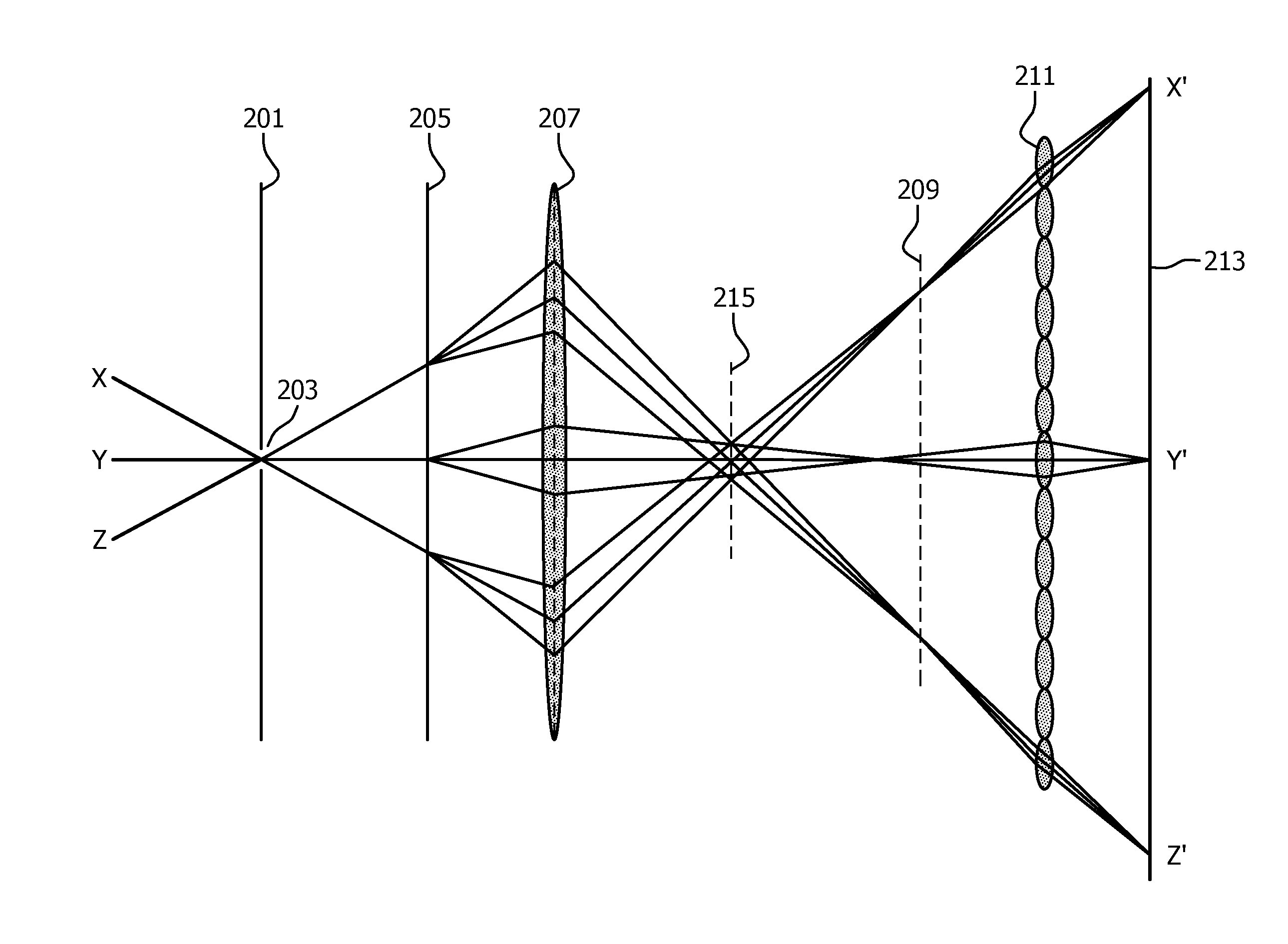
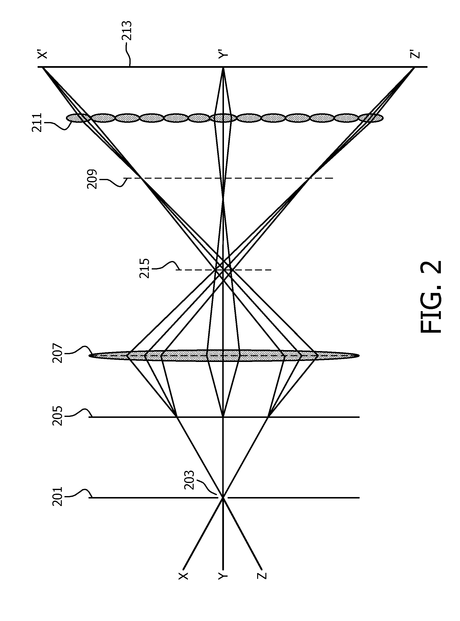
[0066]FIG. 2 illustrates an example of elements of a multi-spectral camera in accordance with some embodiments of the invention.

[0067]The multi-spectral camera comprise a light blocking element 201 which comprises one or more holes 203 that allow light to pass through. For clarity, the following description will focus on an example wherein a pinhole (or a narrow slit) is provided in the light blocking element 201 but it will be appreciated that in other embodiments, more than one hole may be included.

[0068]In the example, the hole 203 has a maximum dimension of less than 1 mm (or for a slit, a width of less than 1 mm). Specifically, the hole 203 is so small that the direction / angle of the light rays from the objects being imaged do not vary more than e.g. 1° across the hole, i.e. rays that originate from the same position can only pass through the hole 203 if they have an angle relative to the hole which is within 1° of each other. In the specific example, the multi-spectral camera ...


PUM


Abstract

A multi-spectral camera comprises a blocking element (201) having at least one hole (203) allowing light through. A dispersive element (205) spreads light from the at least one hole (203) in different wavelength dependent directions and a lens (207) focuses light from the dispersive element (205) on an image plane (209). A microlens array (211) receives light from the lens (207) and an image sensor (213) receives the light from the microlens array (211) and generates a pixel value signal which comprises incident light values for the pixels of the image sensor (213). A processor then generates a multi-spectral image from the pixel value signal. The approach may allow a single instantaneous sensor measurement to provide a multi-spectral image comprising at least one spatial dimension and one spectral dimension. The multi-spectral image may be generated by post-processing of the sensor output and no physical filtering or moving parts are necessary.

Description

FIELD OF THE INVENTION[0001]The invention relates to multi-spectral imaging and in particular, but not exclusively, to generation of multi-spectral images comprising two spatial and one spectral dimension.BACKGROUND OF THE INVENTION[0002]The human eye features three types of cones that are sensitive to different parts of the visible spectrum. These cones are usually designated as L, M and S, referring to the wavelengths they sense (long, middle and short), which roughly correspond to red, green and blue colours. Relative spectral sensitivities of the cones are illustrated in FIG. 1 which illustrates that the cones have a fairly broadband character and correspond to an integration of the light over a wide wavelength range. Consequently, it is possible for two materials with different spectral signatures to appear to the human observer as having the same colour in certain light conditions. This phenomenon is known as metamerism. Similar to the human eye, three primary (RGB) systems em...

Claims


Application Information

Patent Timeline
Patent Type & Authority Applications(United States)
IPC IPC(8): H04N9/07
CPCG01J3/02G01J3/0208H04N9/097G01J3/2803H04N9/045G01J3/0229H04N23/16H01L27/146
Inventor VLUTTERS, RUUDMUIJS, REMCO THEODORUS JOHANNESSCHMEITZ, HAROLD AGNES WILHELMUS
Owner KONINKLIJKE PHILIPS ELECTRONICS NV
Why Eureka
Try Eureka