[0026]Aluminum has been applied as a cost-effective alternative to
copper for the conductors in coaxial cables. However, aluminum
oxide surface coatings quickly form upon air-exposed aluminum surfaces. These aluminum
oxide surface coatings may degrade traditional mechanical, solder and / or conductive
adhesive interconnections.
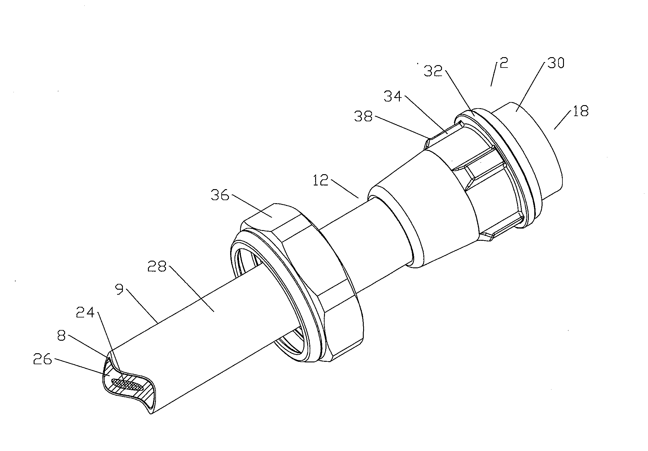
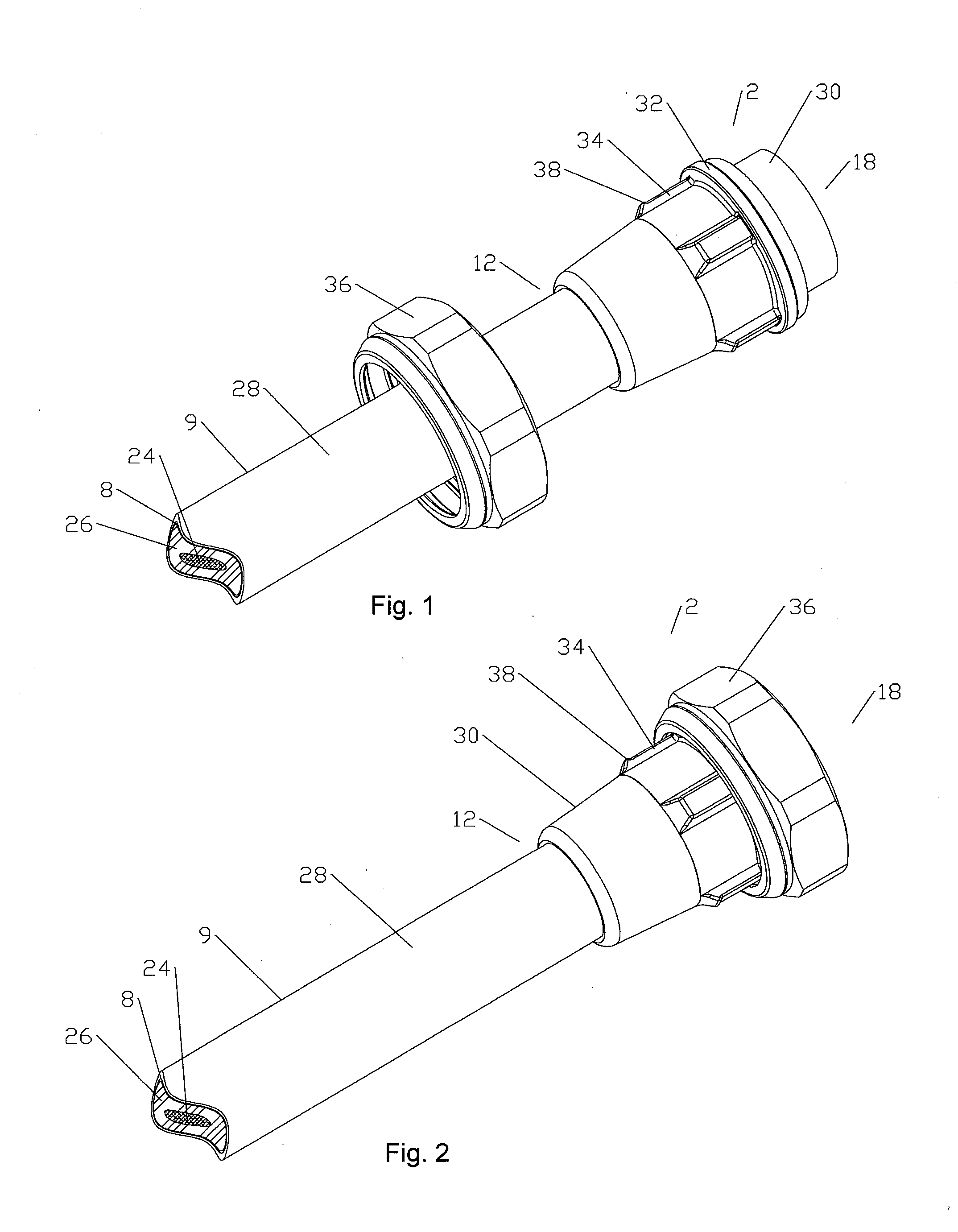
[0034]An overbody 30, as shown for example in FIG. 10, may be applied to the connector body 4 as an overmolding of polymeric material. The overbody 30 increases cable to connector torsion and pull resistance. The overbody 30 may also provide connection interface structure at the connector end 18 and further reinforcing support at the cable end 12, enabling significant reductions in the size of the connector body 4, thereby reducing overall material costs.
[0035]Depending upon the applied connection interface 31, demonstrated in the exemplary embodiments herein as a standard 7 / 16 DIN interface, the overbody 30 may be provided with an overbody
flange 32 and longitudinal support ridges 34 for a
coupling nut 36. The
coupling nut 36 is retained upon the support ridges 34 at the connector end 18 by an overbody
flange 32 and at the cable end 12 by a retention spur 38 provided on at least one of the support ridges 34. The retention spur 38 may be angled toward the connector end 18, allowing the
coupling nut 36 to be placed over the cable 9 initially spaced away from the coaxial connector 2 during
interconnection (see FIG. 1), but then allowing the coupling nut 36 to be passed over the retention spur 38 and onto the support ridges 34 from the cable end 12, to be thereafter retained upon the support ridges 34 by the retention spur(s) 38 (see FIG. 2) in close proximity to the connector interface 31 for connector to connector
mating. The support ridges 34 reduce polymeric
material requirements of the overbody 30 while providing lateral strength to the connector / interconnection 2 as well as alignment and retention of the coupling nut 36.
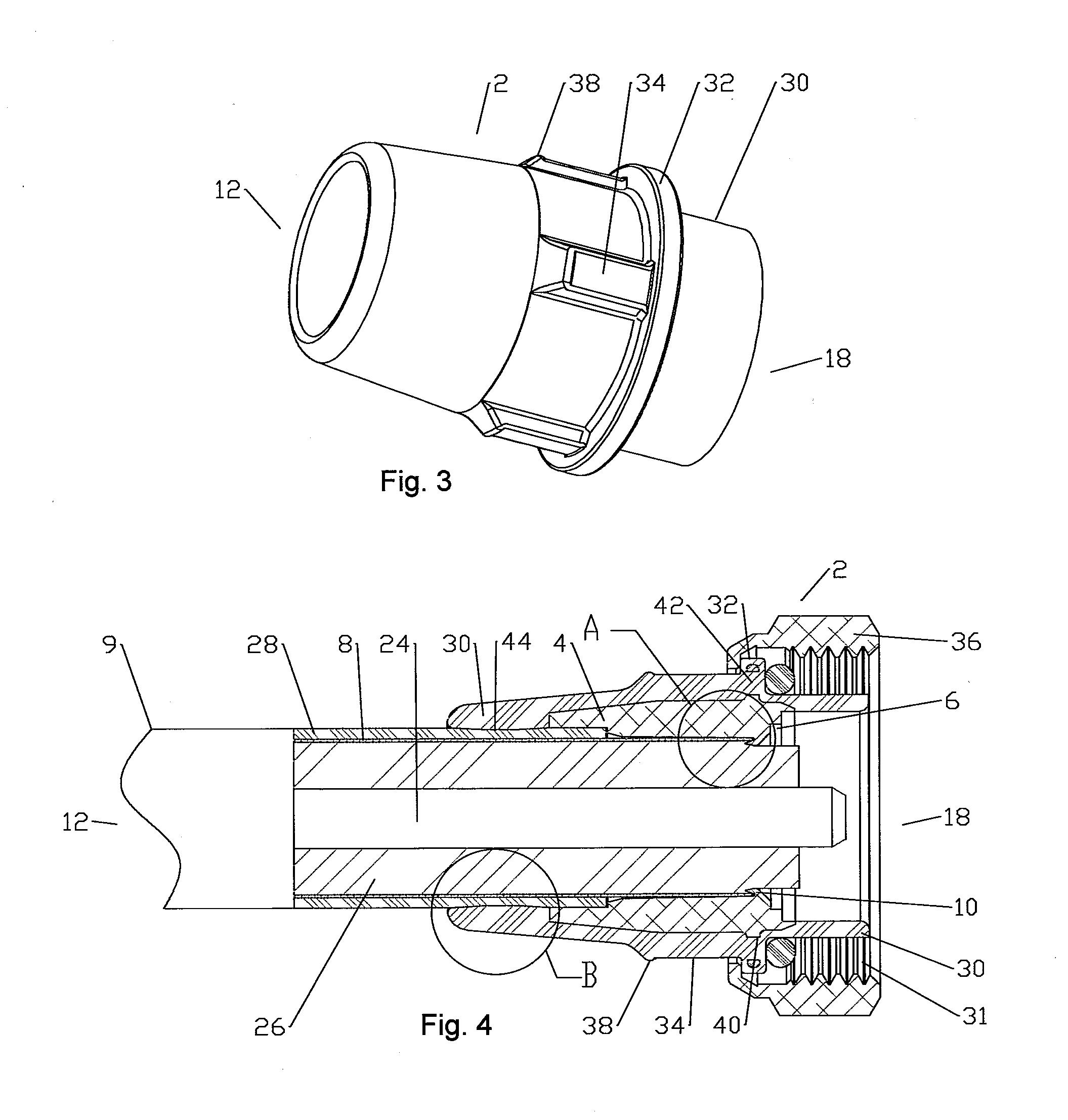
[0036]The overbody 30 may also extend from the connector end 18 of the connector body 4 to provide portions of the selected connector interface 31, such as an alignment cylinder 39 of the 7 / 16 DIN interface, further reducing
metal material requirements of the connector body 4.
[0038]As best shown in FIG. 11, the cable end 12 of the overbody 30 may be dimensioned with an inner
diameter friction surface 44
proximate that of the
coaxial cable outer jacket 28, enabling polymeric
friction welding between the overbody 30 and the outer jacket 28, as the connector body 4 and outer conductor, thereby eliminating the need for environmental seals at the cable end 12 of the connector / cable interconnection. During friction
welding, the coaxial connector 2 is rotated with respect to the cable 9. Friction between the friction surface 44 and the outer
diameter of the outer jacket 28 heats the respective surfaces to a point where they begin to soften and intermingle, sealing them against one another. To provide enhanced friction and allow voids for excess flow due to friction displacement and add key locking for additional strength, the outer jacket 28 and / or the inner
diameter of the overbody 30 may be provided as a series of spaced apart annular peaks of a contour pattern such as a corrugation 46, as shown for example in FIG. 12, or a stepped surface 48, as shown for example in FIG. 13. Alternatively, the overbody 30 may be sealed against the outer jacket 28 with an
adhesive /
sealant or may be overmolded upon the connector body 4 after interconnection with the outer conductor 8, the heat of the injected polymeric material bonding the overbody 30 with and / or sealing against the outer jacket 28.
[0041]One skilled in the art will appreciate that the connector and interconnection method disclosed has significant material cost efficiencies and provides a permanently sealed interconnection with
reduced size and / or weight requirements.Table of Parts2coaxial connector4connector body6bore8outer conductor9cable10shoulder12cable end14friction groove16material chamber18connector end20bore sidewall22friction portion24inner conductor26
dielectric material28outer jacket30overbody31connection interface32overbody
flange34support
ridge36coupling nut38retention spur39alignment cylinder40connector body flange42
interlock aperture43longitudinal knurl44friction surface45notch46corrugation48stepped surface50center cap

