
System and method of conducting refraction angle verification for phased array probes using standard calibration blocks

a phased array and calibration block technology, applied in the field of non-destructive testing and inspection systems, can solve the problems of inability to completely compensate the discrepancy by using only the beam delay in the wedge, the accuracy of the refraction angle verification is not high, so as to achieve high accuracy and consistent results, the effect of efficient operation

Active Publication Date: 2012-05-24
OLYMPUS AMERICA
View PDF5 Cites 20 Cited by
  • Summary
  • Abstract
  • Description
  • Claims
  • Application Information

AI Technical Summary

Benefits of technology

[0015]It is a general object of this invention to provide a system and a method to enable conducting verification of phased array beam angles in an efficient manner with high accuracy.
[0019]It is a further object of the present invention to provide a system and method for verification of PA beam refraction angles that obviates the need to manually write down or marking the beam exit positions on the wedge body used during the procedure.

Problems solved by technology

However, the discrepancy may not be induced by the wedge delays.
Consequently, using only the beam delays in wedge to compensate the discrepancy is not completely reliable.
If the displayed refraction angle is not what the true refraction angle is, the PA instrument may induce errors elsewhere, such as the horizontally measured distance between the measured flaw and the front of the wedge would be nearer or farther than that of the true values.
The above cited procedure of refraction angle check is not practical for phased array operation for multiple reasons, some of which are listed as follows.
Due to the involvement of many different beam angles, it is difficult to physically mark the beam exit point for each beam on the side of the PA search unit.
Due to the nature of the manual operation, the accuracy of the angle verification using the above ANSI Calibration is not desirable.
It is obvious that the above ANSI Calibration operation is time consuming since the user needs to manually write down the angle values and, if necessary, to manually input the values into the PA instrument for further processing.

Method used


Image

  • System and method of conducting refraction angle verification for phased array probes using standard calibration blocks
  • System and method of conducting refraction angle verification for phased array probes using standard calibration blocks
  • System and method of conducting refraction angle verification for phased array probes using standard calibration blocks

Examples


Embodiment Construction

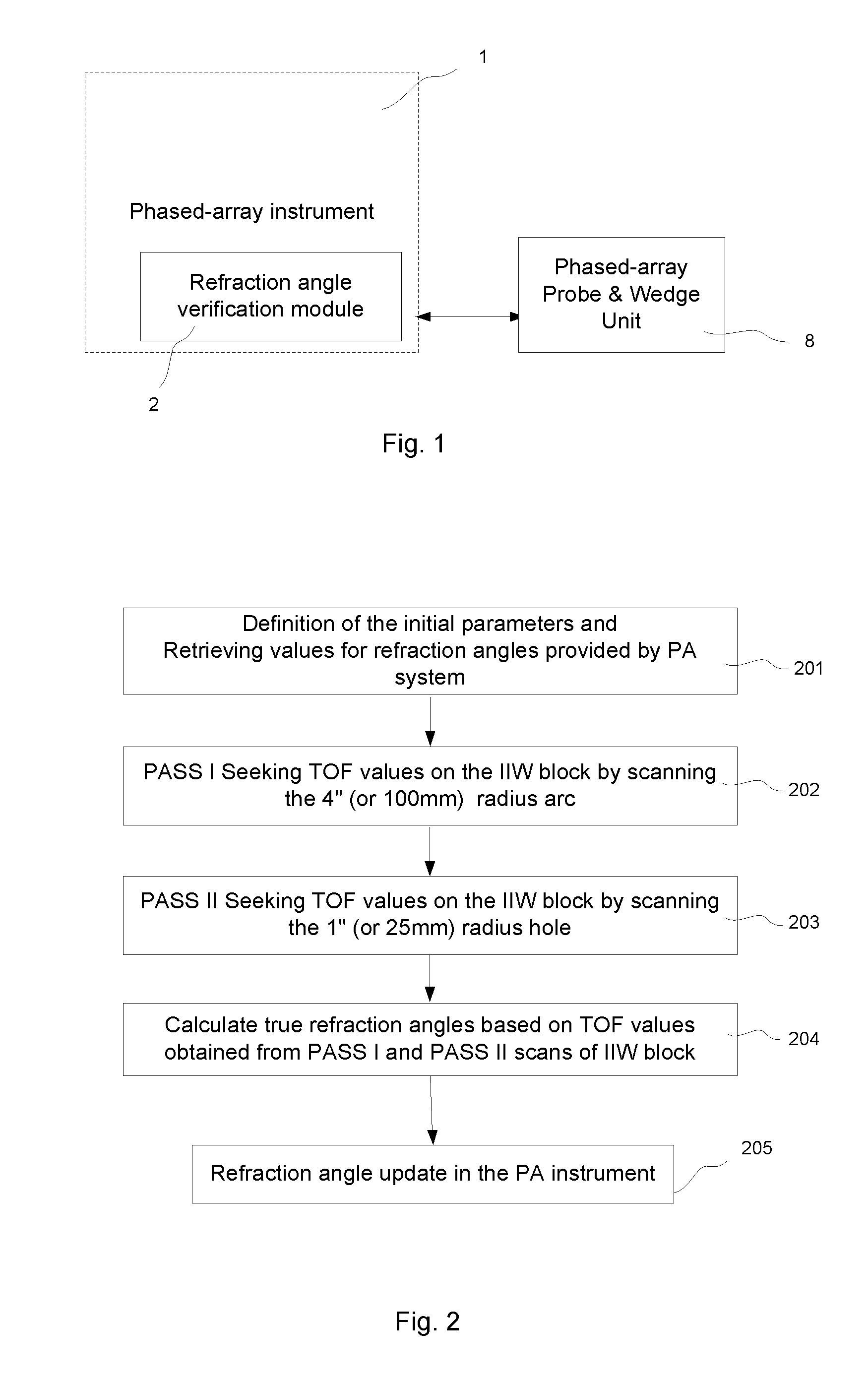
[0032]Referring to FIG. 1, the phased array system with capability of conducting refraction angle verification comprises a conventional phased array system 1, a refraction angle verification module 2 and a conventional phased array probe and wedge unit 8. Angle verification module 2 can be built-in directly onto a phased array system at development stage, or can be a later add-on to an otherwise existing phased array system 1. With module 2 deployed, PA system 1 can be used to verify the refraction angles of probe 8 conveniently with high accuracy.

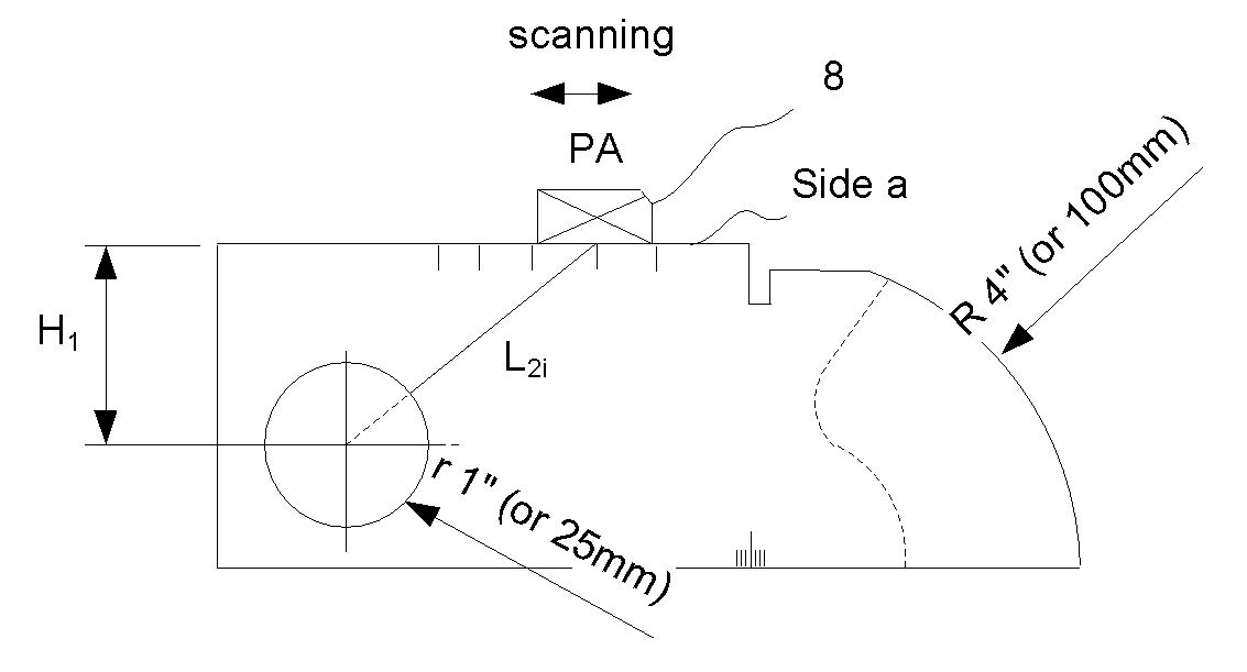
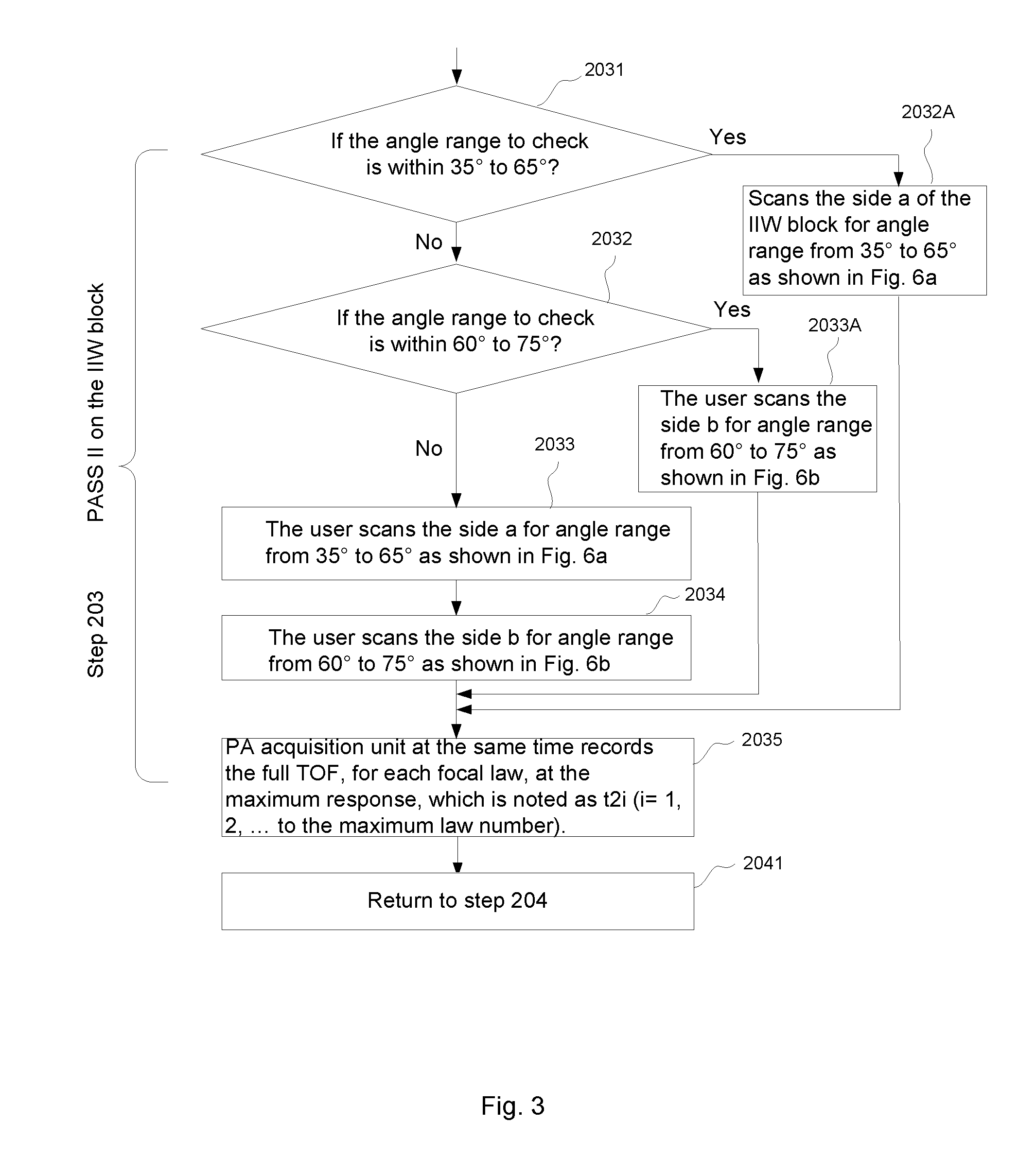
[0033]PA angle refraction verification moduel 2 is preferably deployed by loading executable software onto a processor or equivalent logic processor in other programmable devices (e.g., an ASIC or FPGA chip), installed on the PA system 1. The executable software is designed, according to the present disclosure to execute a refraction angle verification process and method described as follows, associated with FIGS. 2 through 6.

[0034]Accordi...


PUM


Abstract

Disclosed is an ultrasonic phased array non-destructive inspection system that includes a PA probe, a conventional PA inspection unit and a refraction angle verification unit. The PA inspection unit is employed to emit ultrasonic angle beams into an AWS 11W Block and to receive a set of corresponding echo signals reflected from the calibration block and to provide time-of-flight (TOF) values corresponding to each angle beam. The refraction angle verification unit then provides a true angle for each of the angle beams based on the ultrasonic and geometric characteristics of the block and the measured TOF values. Other calibration blocks such as the DSC and Nayships blocks can also be used for this purpose.

Description

BACKGROUND[0001]1. Field of the Disclosure[0002]The present invention relates to non-destructive testing and inspection systems (NDT / NDI), particularly to a system operable for and a method of conducting phased array probes refraction angle verification using standard calibration blocks, including IIW blocks.[0003]2. Related Art[0004]Acoustic phased array (also known as “PA”) instruments provide effective inspection to detect flaws in many kinds of test objects, such as welded steel structures. It is widely known that PA instruments produce accurate, detailed cross-sectional pictures of internal structures at fast inspection speeds. Phased array technology uses multiple acoustic elements and electronic time delays to create beams that can be steered, scanned, swept, and focused electronically for fast inspection and multiple angle inspections.[0005]A PA system is programmed to steer sound beams in a wedge medium and then, being governed by the Snell law, the sound beams propagate th...

Claims


Application Information

Patent Timeline
IPC IPC(8): G01N29/24G01N29/30
CPCG01N29/069G01N29/07G01N2291/267G01N29/30G01N29/262
Inventor ZHANG, JINCHIHABERMEHL, JASON
Owner OLYMPUS AMERICA
Learn More